Surface burners, Assembling the surface burners – LG Studio 30 Inch Slide-In Gas Smart Range Owners Manual User Manual
Page 18
18
INSTALLATION
WARNING
• Do not, under any circumstances, cut or remove
the third (ground) prong from the power cord.
• The customer should have the wall receptacle
and circuit checked by a qualified electrician to
make sure the receptacle is properly grounded.
• The power cord of this appliance is equipped
with a 3-prong (grounding) plug which mates
with a standard 3-prong grounding wall
receptacle to minimize the possibility of electric
shock hazard from this appliance.
• Where a standard two-prong wall receptacle is
encountered, it is the personal responsibility and
obligation of the customer to have it replaced
with a properly grounded three-prong wall
receptacle.
• Ensure proper ground
a
exists before use.
• Do not use an adapter plug. Disconnecting of
the power cord places undue strain on the
adapter and leads to eventual failure of the
adapter ground terminal.
• Installation must conform with local codes or, in
the absence of local codes, with the National
Fuel Gas Code, ANSI Z223.1/NFPA 54 or, in
Canada, the Natural Gas and Propane
Installation Code, CSA B149.1.
NOTE
• Ground Fault Circuit Interrupters
- GFCI’s are not required or recommended for
gas range receptacles.
- Ground Fault Circuit Interrupters (GFCI’s) are
devices that sense leakage of current in a
circuit and automatically switch off power
when a threshold leakage level is detected.
These devices must be manually reset by the
consumer. The National Electrical Code
requires the use of GFCI’s in kitchen
receptacles installed to serve countertop
surfaces.
- Performance of the range will not be affected
if operated on a GFCI-protected circuit but the
occasional resetting of the circuit can become
an annoyance.
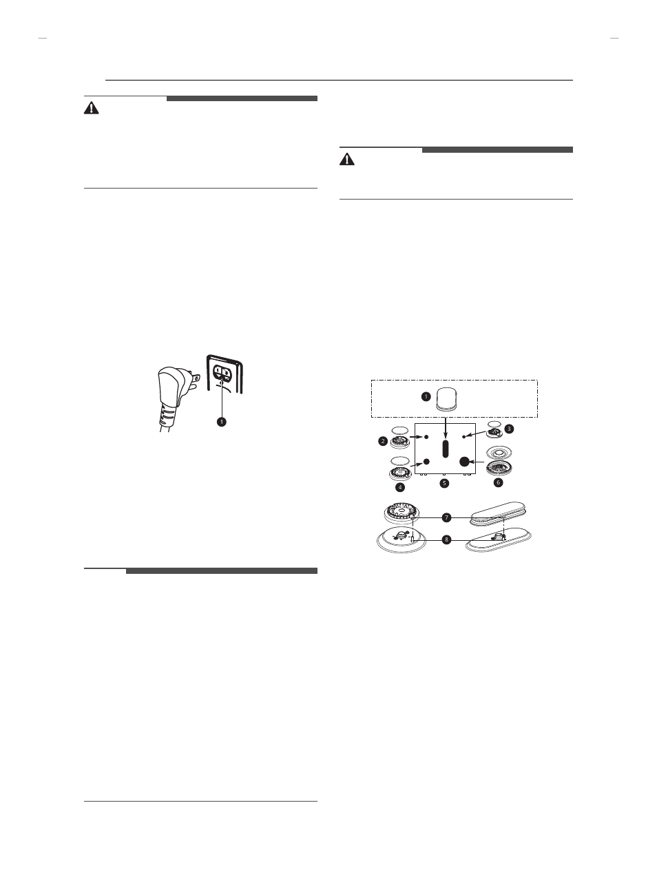
Surface Burners
Assembling the Surface Burners
CAUTION
• Do not operate the burners without all parts in
place.
1
Place the burner caps and heads on the
cooktop.
• There are one small, one medium, one
large, one oval(center), and one extra large
burner head and cap.
2
Make sure that the caps and heads are placed
in the correct locations.
3
Make sure the hole in the burner head is
positioned over the electrode.
a
Oval (Center) burner head/cap assembly
b
Medium burner head and cap
c
Small burner head and cap
d
Large burner head and cap
e
Front of range
f
Dual burner head and cap
g
Hole
h
Electrode
UUGGwGX_GG{ SGhGY[SGYWYXGG[aXXGwt