0 designing an evf/evh cluster (cont’) – Electro-Voice EVF/EVH EVF-1151S User Manual
Page 15
Electro-Voice EVF/EVH User Manual
15
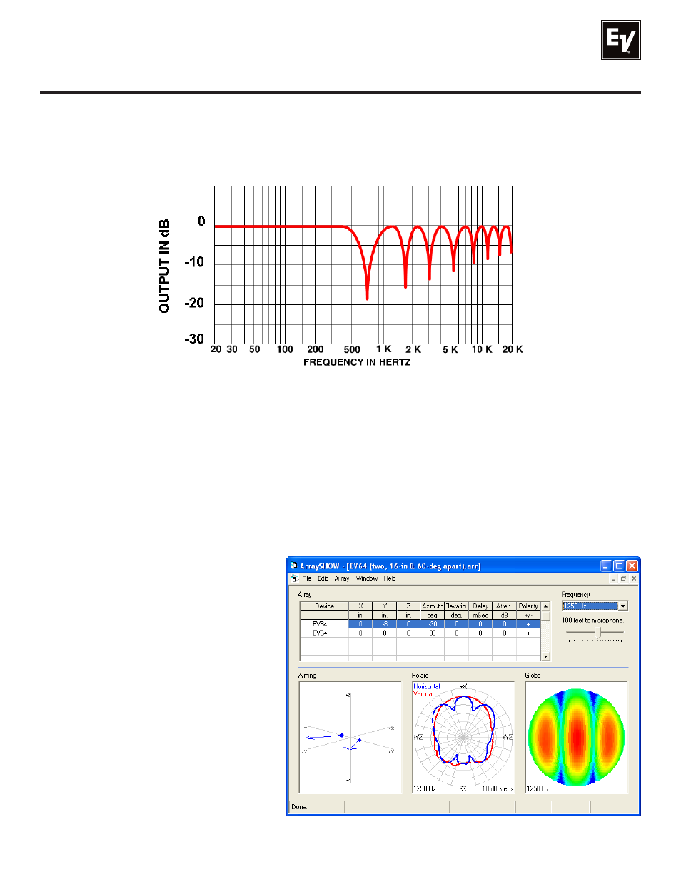
Figure 5:
Typical response off the array axis of the two loudspeakers shown in Figure 4,
showing cancellations due to arrival-time differences
This effect is shown in the frequency-response of Figure 5. Given the dimensions of the typical compact
loudspeaker systems and when they are clustered in close proximity to one another, the first several in-
terference nulls occur right in the middle of the vocal range. A frequency response with these ever-more-
closely spaced nulls is known as a “comb filter” response, after the visual appearance of the response.
3.0 Designing an EVF/EVH Cluster (cont’)
If one of the null frequencies is chosen and the horizontal polar response is measured, the result is shaped
like the blue polar response in the center lower graph of Figure 6. In this view, the cluster axis points up
(+X). Full output is achieved on this axis, since both signals arrive at the same time. But there are off-axis
problems. While the overall coverage of the cluster is about 120° (6 dB down), two deep nulls occur at
about 20° on either side of the cluster axis.
Figure 6:
Horizontal polar response (blue center
plot) of two closely clustered 60° x 40°
loudspeakers aimed 60° apart, showing
the off-axis nulls at 1,250 Hz caused by
multiple-source interference
(see text for more details)
NORMALIZED
- EVF/EVH EVF-2121S EVF/EVH EVF-1122S EVF/EVH EVH-1152D EVF/EVH EVF-1121S EVF/EVH EVF-1181S EVF/EVH EVF-1152S EVF/EVH EVF-1122D EVF/EVH EVF-1152D EVF/EVH EVH-1152S EVF/EVH EVF-2151D EVF-1152S Single 15" 2-Way Full-Range Indoor Loudspeaker System (EVCoat-Finish, White) EVF-1122D Single 12" 2-Way Full-Range Indoor Loudspeaker System (EVCoat-Finish, White) EVF-1181S Single 18" Front-Loaded Indoor Subwoofer System (EVCoat-Finish, White)