Epson C82315 User Manual
Page 35
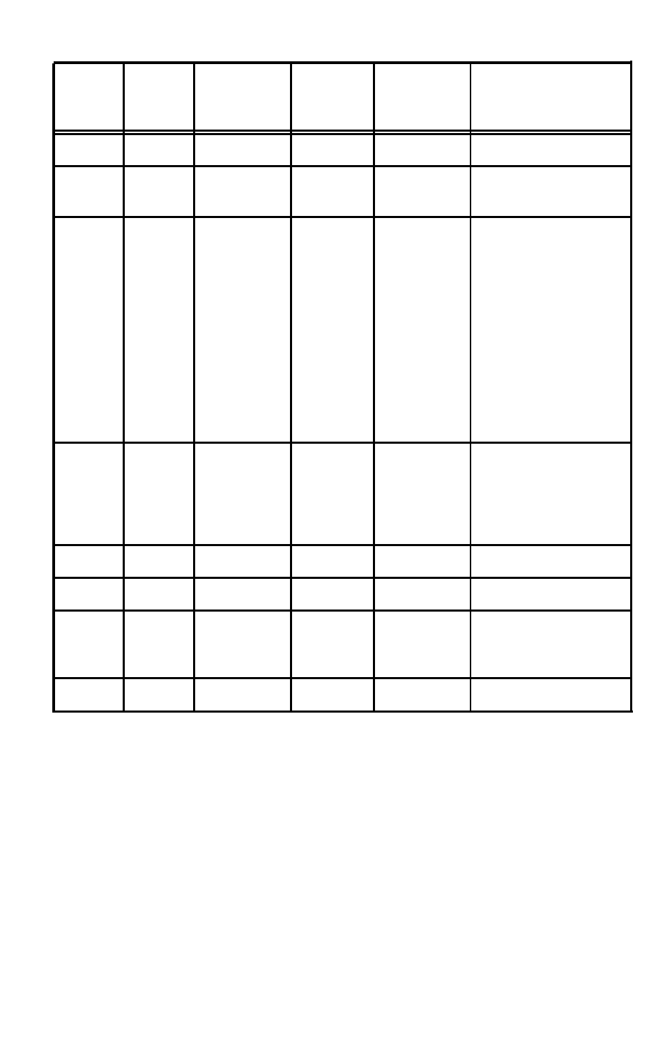
Signal
Return
Signal
Parallel
Direction
Description
Pin
Pin
Cable
Pin
18 -
NC
19-30 -
GND
21-24
Not used
Twisted
pair
ground
returns listed above
31
INIT
16
IN
Defined to reset and
dear the printer
when
LOW: THE RE-
SET AND CLEAR
ARE NOT SUP-
PORTED BY THE
C82315*, As the IBM
host cannot be in-
terrupted by this
signal. An ACKNLG
is generated for
handshaking.
32 -
ERROR
15
OUT
This signal goes
LOW when the
printer is in an error
state such as out Of
p a p e r .
33 -
GND
25
Logic ground
34 -
NC
Not
used
35 -
HIGH
Pulled up to +5v
through a 3.3K ohm
resistance
36 -
SLCTIN
17
NOT SUPPORTED
NOTE:
The parallel connector is a DDK type DHA-36 or equivalent.
The column heading ‘DIRECTION’ refers to the direction of signal flow as viewed
from the C82315* interface.
‘RETURN’ denotes the twisted-pair return, to be connected at signal ground level.
For the interface wiring. be sure to use twisted-pair cable for each signal and to
complete the connection on the return side. The cable should be shielded and
connected to the chassis of the host computer and printer.
All interface conditions as based on TTL levels. Both the rise and the fall times
of each signal must be less than 0.2 u sec.
28