Setting the jumpers – Epson C82315 User Manual
Page 11
Also, because this interface can be damaged by static electricity, you should
prepare the interface card for installation according to the procedure below:
1. While the interface is still in its anti-static bag, place it next to your printer.
2. Place the twin-axial cable from the host computer on top of the anti-static bag;
make sure the metal connector on the cable is in contact with the bag.
3. Remove the interface card
from the
bag
and place it on top of the bag next to
the twin-axial cable.
4. Set the jumpers on the interface card according to the instructions
in the
following section.
SETTING THE JUMPERS
A jumper is a small, square plastic object that fits over two terminals (prongs) on
the interface card.
To
connect a jumper, place the jumper over both terminals. To
disconnect a jumper, place it over one terminal only. All jumpers are connected
when shipped from the factory.
The C82315* interface card has three jumpers, labeled as J2, J5, and J6. The
settings for J5 and J6 are different for the different emulations. After deciding on
an emulation, set the jumpers according to the tables below.
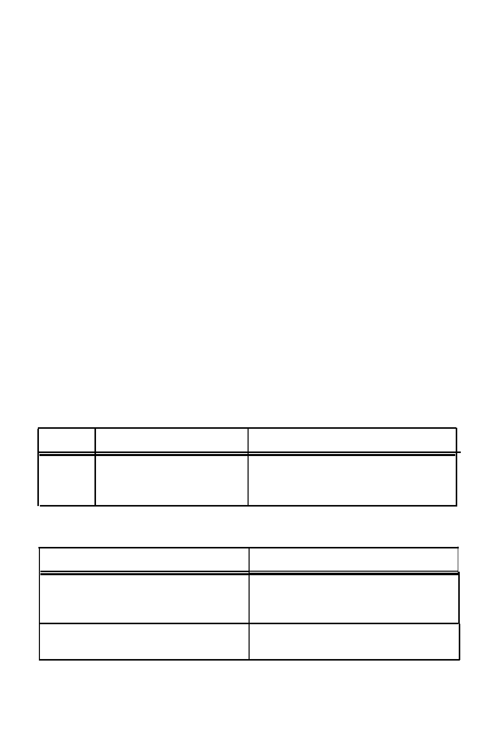
Applies to all emulations
Jumper
Connected
Disconnected
J2
Normal twin-axial cable
Twisted-pair ‘passive star panel’ cable
Use only if problems found on this type
of cable.
Dot-matrix 4214/5224 printer emulation
I
Jumper
Connected
Disconnected
J 5
Sends a printer ID code for
Sends a printer ID code for an IBM 5224
an IBM 4214 model 2 to the
model 1 to the host
host
J6**
Sends Epson ESC/P 9-pin
Sends Epson ESCIP 24145pin LQ com-
FX Commands to the printer
mands to the printer
4