Panel descriptions – Roland AIRA SYSTEM-8 PLUG-OUT Synthesizer User Manual
Page 4
4
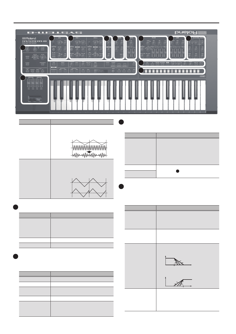
Panel Descriptions
Controller
Explanation (for variation 1)
[RING] button
(OSC 2 only)
This is a ring modulator. It generates a
complex waveform by multiplying OSC 1
and OSC 2.
OSC 1
OSC 2
[SYNC] button
(OSC 2 only)
This is oscillator sync. It generates a
complex waveform by forcibly resetting
OSC 2 to the beginning of its cycle in
synchronization with the OSC 1 frequency.
OSC 1
OSC 2
4
OSC 3/SUB OSC
Controller
Explanation
Wave knob
Selects the waveform that is the basis of
the sound.
R
(Sine wave), -1Oct, -2Oct,
S
(Triangle wave), -1Oct, -2Oct
[COLOR] knob
The result depends on the waveform.
[TUNE] knob
Adjusts the pitch of the oscillator.
5
MIXER
Here you can adjust the volume of OSC 1, OSC 2, OSC 3/sub-
oscillator, and noise.
Controller
Explanation
[OSC 1] knob
Adjusts the volume of the OSC 1.
[OSC 2] knob
Adjusts the volume of the OSC 2.
[OSC 3/SUB OSC]
knob
Adjusts the volume of the OSC 3/sub-
oscillator.
[NOISE] knob
Adjusts the volume of the noise.
[NOISE TYPE]
button
Selects the type of the noise.
Lit:
white noise
Unlit:
pink noise
6
PITCH
Here you can create time-varying change (envelope) for pitch.
Controller
Explanation
[ENV] knob
If this knob is turned toward the right, the
pitch initially becomes higher and then
returns to the pitch of the key you pressed.
If this knob is turned toward the left, the
pitch initially becomes lower and then
returns to the pitch of the key you pressed.
[A] slider
These sliders operate similarly to the [A][D]
sliders of the
8
AMP
section (they affect
the pitch rather than the volume).
[D] slider
7
FILTER
These settings determine the brightness and thickness of the
sound. Here you can also specify the time-varying change
(envelope) for the filter.
Controller
Explanation (for variation 1)
[VARIATION] knob
Selects the variation of the FILTER section.
&
For an explanation of variations 2 and
following, refer to “Reference Manual”
(PDF).
[CUTOFF] knob
Specifies the cutoff frequency of the filter.
This knob is a GRF (GRIFFER) knob which
allows high-precision adjustments.
Filter type knob
Selects the slope of the filter.
LPF:
-24 dB, -18 dB, -12 dB
-18 dB
-12 dB
-24 dB
Level
Frequency
HPF:
-12 dB, -18 dB, -24 dB
-18 dB
-12 dB
-24 dB
Level
Frequency
[RESO] knob
Resonance boosts the sound in the region
of the filter’s cutoff frequency.
Higher settings produce stronger
emphasis, creating a distinctively
“synthesizer-like” sound.
1
2
3
4
5
6
7
8
9
11
12
10