Appendix a rj-45 pin assignment and cable system, Appendix b frequently asked question – PLANET POE-100SK User Manual
Page 2
- 9 -
- 10 -
- 11 -
- 12 -
- 13 -
- 14 -
4.3 POE-100S – the splitter installation
1. Adjust the output voltage of POE-100S by moving the
switch to correct position, i.e. 12V, 9V, or 5V.
Caution
Do not adjust the output voltage of POE-
100S while it is powered on. (i.e. PWR LED is
steady light green).
Figure 4: Output voltage switch on POE-100S
2. Connect a standard network cable from “Ethernet+DC” of
POE-100 to “Ethernet+DC” of POE-100S. The power LED
of POE-100S will be steady on.
Figure 5: Connection to POE-100S
Appendix A
RJ-45 pin assignment and cable system
A.1 Pin assignment
The following table and diagram show the standard RJ-45
receptacle/ connector and their pin assignments:
RJ-45 Connector pin assignment
Contact
MDI Media Dependant
Interface
MDI-X Media Dependant
Interface -Cross
1
TX + (transmit)
Rx + (receive)
2
TX - (transmit)
Rx - (receive)
3
Rx + (receive)
TX + (transmit)
4,5
Ground*
6
Rx - (receive)
TX - (transmit)
7,8
DC current*
Table A-1 The standard cable, RJ-45 pin assignment
Figure A-1 The standard RJ-45 receptacle/connector
Warning
Do not connect the cable from
“Ethernet + DC” of POE-100 to
remote device, otherwise the
inner component of remote
device
may
permanently
malfunction.
3. Connect the UTP cable in the package from “Ethernet” of
POE-100S to the RJ-45 port of remote device.
4. Connect proper DC plug from “DC OUT” of POE-100S to
remote device.
Caution
Please ensure the output voltage is correct
before applying power to remote device.
5. Power on the remote device.
POE-100
POE-100S
100 meters
WAP-1965
Data
Data
Power + Data
Power
Power
Remote Device
Figure 6: Connection architecture
?
Remark:
1. DC current and voltage varies on the DIP-
switch selection of POE-100S.
2. Gigabit Ethernet is not allowed to use POE-
100 products since pair 4,5 and pair 7, 8 are
all being used. Only 10Base-T and 100Base-
TX can apply with POE-100/100S products.
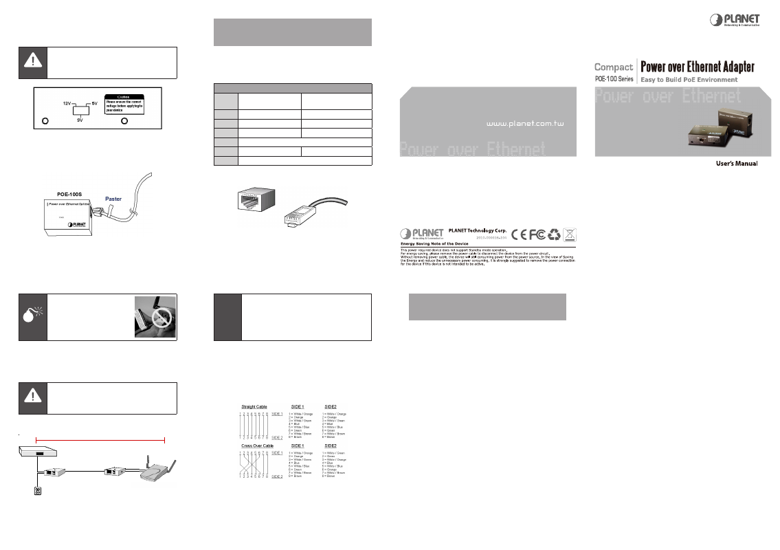
A.2 Cable system
The standard RJ-45 receptacle/connector
There are 8 wires on a standard UTP/STP cable and each
wire is color-coded. The following shows the pin allocation
and color of straight cable and crossover cable connection:
Figure A-2: Straight-Through and Crossover Cable
Please make sure your connected cable is with same pin
assignment and color as above picture before deploying the
cables into your network.
Appendix B
Frequently Asked Question
1. What’s the correct step to apply the power to the
remote device?
Ans:
a. Please make sure the POE-100S is set to the correct DC
output voltage in advance.
b. Connects the remote device to POE-100S, both power
plug cable and Ethernet cable.
c. Plug-in the 15VDC power to the POE-100 and check the
LED on it.
d. Plug-in the UTP cable from POE-100 into the “Ethernet
+ DC” port of POE-100S. The LED on POE-100S should
turns on. And the remote device starts to boot up.
e. IF you would like to change the voltage, please
DO
remove the cable from the port “Ethernet + DC” of POE-
100S. Make sure the LED of POE-100S is turned off to
adjust the voltage output.
2. How many remote Ethernet devices can be powered?
Ans:
a. Due to POE-100/100S only provide one Ethernet inter-
face, only one Ethernet device can be powered.
b. For safety reason, POE-100/100S will only support device
with power consumption below 12watts. Please make
sure the remote Ethernet device is under the range of
12V 1A, 9V 1.2A or 5V 2A, that with power consumption
below 12 watts.
3. Can I connect POE-100 or POE-100S to other
IEEE802.3af device?
Ans:
a. POE-100 and POE-100S is not comply with IEEE802.3af,
you can not connect any of it to an IEEE802.3af devices.
b. For POE-100 it will inject power all the time. This means
it will send power once it is connect with 15VDC AC
adapter. So, please DO NOT connect the UTP cable from
POE-100’s “Ethernet+DC” to any Ethernet equipment
directly including any IEEE802.3af complied device.
c. Not an IEEE802.3af complied device, POE-100S will not
detect and reply the signal from 802.3af injector. As a
result, the Power LED will never turns on if you connect
to an IEEE802.3af injector and will never power the
remote device as well.