PLANET POE-100SK User Manual
Introduction, Features & specifications, Package contents
- 1 -
- 2 -
- 3 -
- 4 -
- 5 -
- 6 -
- 7 -
- 8 -
1. Introduction
Thank you for purchasing our Power over Ethernet Adapter.
This user's manual is to provide the installation and usage
of this adapter for network installers and users.
PLANET's PoE products include two models: Injector and
Splitter. Injector inserts current into the unused wires in
a standard network cable (pin: 4, 5, 7, 8). So the cable
between Injector and Splitter can transfer power and
network signals simultaneously. Base on the limitation of
cable on Ethernet and Fast Ethernet, the maximum distance
between the two devices including Injector and Splitter can
reach 100 meters.
3. Features & Specifications
3.1 Features
• Provides low-voltage DC power over existing Category 5
cabling to a device with an Ethernet port
• Distance up to 100 meters
• Protects devices from possible damages due to power-
surges
• Three different output voltage options (5V/2A, 9V/1.2A,
12V/1A) to fit various devices
• Work with EIA568, category 5, 4-pair cable for 10Base-T
or 100Base-TX, Ethernet / Fast Ethernet network
The POE-100S separates the power out and will provide
three kind of power output, in different voltage and current,
i.e. 5VDC/ 2A, 9VDC/1.2A and 12VDC/1A.
Hint
Please check the power requirement of the
device that is going to get power from POE-
100S. If the power requirement is higher than
POE-100/100S can supply, it will shutdown the
POE-100S. This shall shutdown your device as
well.
POE-100 and POE-100S should being installed in pair, use
of third-party device could damage your device or use of
only one device at a time could damage your device.
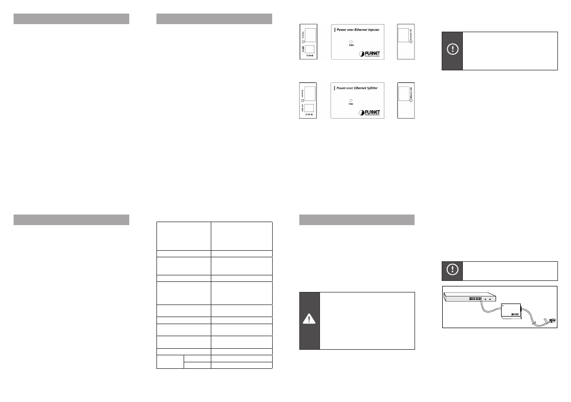
3.3 Product Outlook
Figure 1: POE-100
Figure 2: POE-100S
2. Package Contents
Your Power over Ethernet Device contains the following
in the package:
Model: POE-100SK
• Power over Ethernet Injector (POE-100) x 1
• Power over Ethernet Splitter (POE-100S) x 1
• Power Adapter x 1
• User’s Manual x 1
• Reminder Paster x 1
• Straight 15cm UTP cable x 1
• DC plug cable x 3
Model: POE-100
• Power over Ethernet Injector (POE-100) x 1
• Power Adapter x 1
• User’s Manual x 1
• Reminder Paster x 1
Model: POE-100S
• Power over Ethernet Splitter (POE-100S) x 1
• User’s Manual x 1
• Straight 15cm UTP cable x 1
• DC plug cable x 3
Please consult your local dealer if any of the parts is
missed.
3.2 Technical Specification
Ethernet connector
2 x RJ-45
POE-100:
Ethernet, Ethernet+ DC out
POE-100S:
Ethernet, Ethernet + DC in
Ethernet data rate
10/100Mbps
Power usage of Category
5 pin assignment
(Ethernet + DC)
-: Pin 4, 5
+: Pin 7, 8
Input voltage, current
POE-100: 15VDC, 1A min.
Output voltage, current
POE-100S:
DC 5V, 2A
DC 9V, 1.2A
DC 12V, 1A
DIP Switch
POE-100S:
1 for DC voltage selection
LED indication
1 power LED indicator
Number of Ethernet
devices can be powered
1
Ethernet data cable
TIA/EIA-568, Category 5
cable
Dimensions (L x W x H)
64.5mm x 42.3mm x 20.4mm
Operating
environment
Temperature 0~50 degree C
Humidity
5~95% (non-condensing)
4. Hardware Installation
4.1 Prior installation
Before your installation, it is recommended to check your
network environment. If there is problem for you to install
a networked device where it is very difficult to find a power
socket for your AC-DC Adapter, POE-100 and POE-100S
should provide you a way to provide DC power for this
Ethernet Device conveniently and easily.
The POE-100 comes with an AC-DC adapter with 15VDC
output and injects this DC power into the un-used pin of
the twisted pair cable (pair 4,5 and pair 7,8).
Caution
1. Power over Ethernet (POE-100 and POE-
100S) will only work under Category 5
UTP/STP cable with 4-pair. Please refer to
appendix A for more.
2. Gigabit Ethernet device CANNOT be used
to work with POE-100 and POE-100S since
1000Base-T will use the 4-pair for data
transmission. Plug in Gigabit device to
Ethernet port of POE-100/100S will force the
port to link at 10/100Mbps.
4.2 POE-100 – the injector installation
1. Connect a standard network cable from Hub/Switch to
Ethernet port of POE-100.
2. Connect the long cable that will be used to connect to
the remote device to the port Ethernet+DC.
3. In the other end of the cable, place the warning paster
to the RJ-45 end.
Hint
This warning paster is used to warn the users
if they are going to make change of the cable.
PWR
Power over Ethernet Injector
POE-100
SWITCH
Paster
Figure 3: Warning paster location
4. Connect the AC adapter to “15V DC” of POE-100. The
power LED will be steady on.