PLANET IPOE-E174 User Manual
Page 16
16
Step 3: Use the screws to screw the wall-mount plate on the
Industrial Power over Ethernet Extender.
Step 4: Use the hook holes in the corners of the wall-mount plate to
hang the Industrial Gigabit Ethernet Switch on the wall.
Step 5: To remove the wall-mount plate, reverse the steps above.
2.4 Connecting IPOE-E174 to Power Source Equipment
(PSE)
This section describes how to install the Industrial Power over Ethernet
Extender and make connections to it. Please read the following topics
and perform the procedures in the order being presented.
There are five RJ45 ports in the Industrial Power over Ethernet
Extender, of which the “PoE IN” port functions as “PoE (Data
and Power) input” and the “PoE In-Use” port on the other side
functions as “PoE (Data and Power) output”.
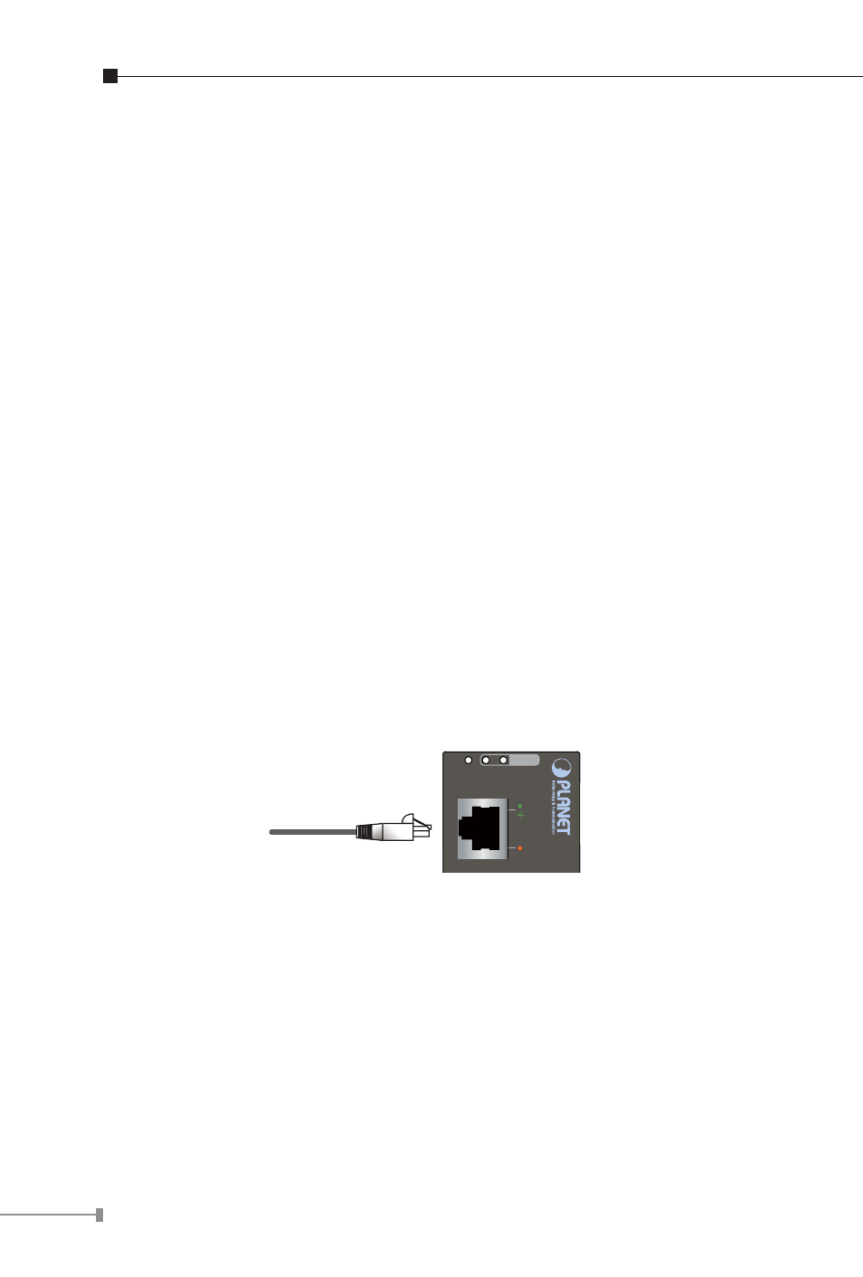
Step 1: Connect a standard CAT-5e/6 UTP cable from Power Source
Equipment (PSE), such as PoE Switch, PoE injector hub and
single port PoE injector, to the “PoE IN” port of the IPOE-
E174.
4-P
PWR
Midspan IN Endspan IN
60W PoE
ACT
LNK
PoE IN