3 switch upper panel – PLANET IGS-504HPT User Manual
Page 15
15
100/1000BASE-X SFP Interfaces (IGS-624HPT)
LED
Color
Function
LNK/ACT Green
Light: indicates the Switch is successfully connecting to the
network at 100/1000Mbps.
Blink: indicates that the Switch is actively sending or
receiving data over that port.
OFF: indicates that the Switch is inactively sending or
receiving data over that port.
Per PoE Power Usage (Unit : Watt) (Lower LED to upper LED)
LED
Color
Function
30
Orange
Light: indicates the system is providing >30/60/90/120W PoE
power usage.
Blink: indicates the system is providing 30/60/90/120W PoE
power usage.
25 < X < 30, 30W LED flash; X >= 30, 30W LED light;
55 < X < 60, 60W LED flash; X >= 60, 60W LED light;
85 < X < 90, 90W LED flash; X >= 90, 90W LED light;
100 < X < 115, 120W LED flash;
115 < X < 120, 120W LED flash fast; X >= 120, 120W LED light.
60
90
120
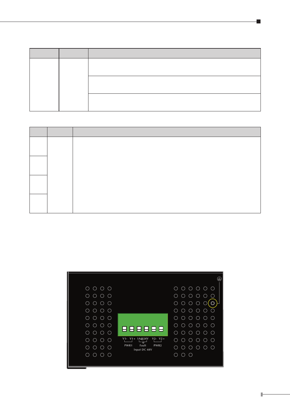
2.1.3 Switch Upper Panel
The upper panel of the Industrial Gigabit PoE+ Switch consists of one terminal
block connector within two DC power inputs. Figure 2-2 shows the upper panel of
the Switch.
Figure 2-2 shows upper panel of Industrial Gigabit PoE+ Switch.
1 2 3 4 5 6
Figure 2-2: Industrial Gigabit PoE Switch Upper Panel.