A.3 fiber optical cable connection parameter, Straight cable side 1 side2, Crossover cable side 1 side2 – PLANET FSD-805 User Manual
Page 18: Standard fiber type cable specification
1
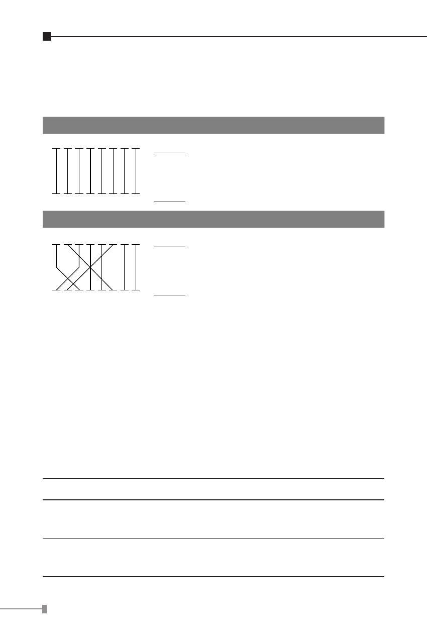
There are 8 wires on a standard UTP/STP cable and each wire is
color-coded. The following shows the pin allocation and color of
straight cable and crossover cable connection:
Straight Cable
SIDE 1
SIDE2
1
2
3
4
5
6
7
8
1
2
3
4
5
6
7
8
SIDE 1
SIDE 2
1 = White / Orange
2 = Orange
3 = White / Green
4 = Blue
5 = White / Blue
6 = Green
7 = White / Brown
8 = Brown
1 = White / Orange
2 = Orange
3 = White / Green
4 = Blue
5 = White / Blue
6 = Green
7 = White / Brown
8 = Brown
Crossover Cable
SIDE 1
SIDE2
1
2
3
4
5
6
7
8
1
2
3
4
5
6
7
8
SIDE 1
SIDE 2
1 = White / Orange
2 = Orange
3 = White / Green
4 = Blue
5 = White / Blue
6 = Green
7 = White / Brown
8 = Brown
1 = White / Green
2 = Green
3 = White / Orange
4 = Blue
5 = White / Blue
6 = Orange
7 = White / Brown
8 = Brown
Figure A-1: Straight-Through and Crossover Cable
Please make sure your connected cables are with same pin
assignment and color as above picture before deploying the
cables into your network.
A.3 Fiber Optical Cable Connection Parameter
The wiring details are as below:
n Fiber Optical patch Cables:
Standard
Fiber Type
Cable Specification
100Base-FX
(1300nm)
Multi-mode
50/125μm or
62.5/125μm
100Base-FX
(1310nm)
Single-mode
9/125μm