Termination control connector j4, Led description – Avago Technologies LSI53C120 User Manual
Page 17
LSI20101/LSI20102 SCSI Bus Boards
9
2.4.4 LEDs and Connector J4
The LSI20101 board contains three LEDs: one bus activity LED and two
SCSI TERMPWR status LEDs.
One green LED (CR5) indicates the state of the SCSI Bus Busy signal.
Two yellow LEDs (CR6 for A-side and CR3 for B-side) indicate when
TERMPWR is shorted to ground. For instance, if TERMPWR is grounded
somewhere in the subsystem while TERMPWR is supplied by the board
(when U4 switches SW1 and/or SW2 are ON) the LED will light. See
Connector J4, pins 5 and 6, is an LED interface that contains the signal
and return for the SCSI active LED. An external LED harness can be
connected to the board for external mounting of a SCSI active LED. See
Table 4
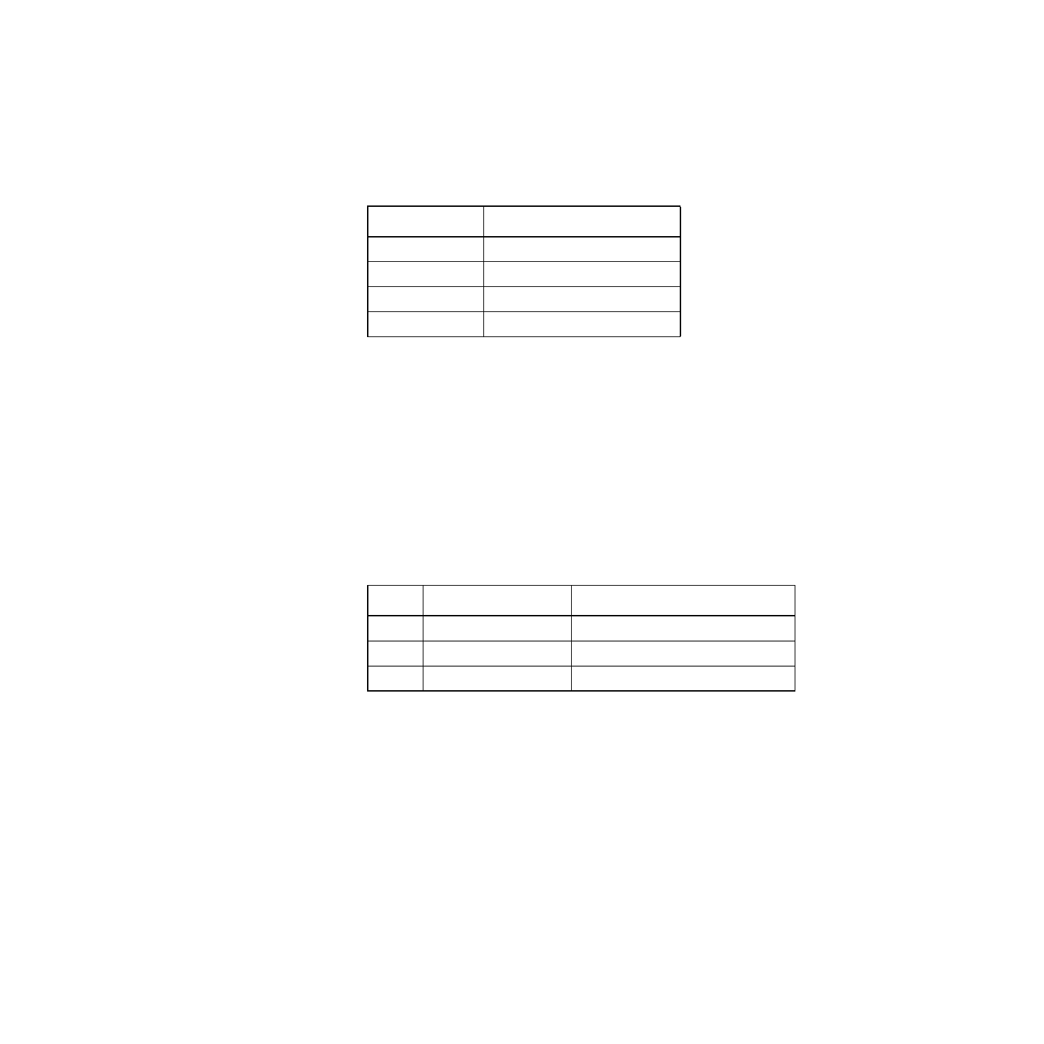
Termination Control Connector J4
J4-Pin Number
Signal Name
1
Disable SE-A TERM
2
GND
3
Disable SE-B TERM
4
GND
Table 5
LED Description
LED
Color/Condition
Description
CR3
Yellow/ON
B-Side, TERMPWR shorted to ground
CR5
Green/ON
A-Side, BUSY (SCSI active on Side-A)
1
1. If the SCSI busy signal is active on A-side, it will also be active on B-side and
vice versa.
CR6
Yellow/ON
A-Side, TERMPWR shorted to ground