Avago Technologies MegaRAID SAS 9265-8i User Manual
Page 5
LSI Corporation
|
December 2010
Page 5
MegaRAID SAS 9265-8i RAID Controller Quick Installation Guide
Installing the Controller
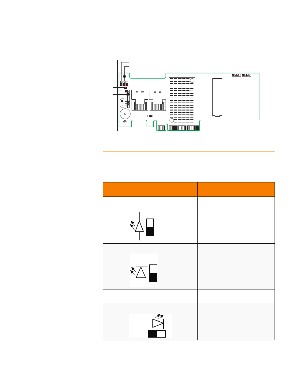
Figure 2: Layout of the MegaRAID SAS 9265-8i RAID Controller
NOTE: Pin 1 on the headers and connectors is highlighted in red in
.
describes the jumpers and the connectors on the RAID controller.
Table 1:
Jumpers and Connectors
Jumper/
Connector
Type
Description
J1A1
Global drive fault LED header
2-pin connector
Connects to an LED that indicates whether
a drive is in a fault condition.
J1A2
Write pending LED header
2-pin connector
Connects to an LED that indicates when
the data in the cache has yet to be written
to the storage devices. Used when the
write-back feature is enabled.
J1A3
LSI Test header
2-pin connector
Reserved for internal use.
J1A4
Activity LED header
2-pin connector
Connects to an LED that indicates activity
on the drives connected to the controller.
85079-00
J2B1
J2B2
J1A1
J1A2
J1A3
J1A4
J1A5
J1A7
J2B3
J2B4
J5B1
J5A1 J6A1
J1A1
ak
+ve
-ve
J1A2
ak
+ve
-ve
J1A4
+ve
a
k
-ve