Power switch – Amprobe BDM40-UA Bench-Digital-Multimeter User Manual
Page 7
6
will only get this indication of an energized circuit if the power in the circuit is negative with respect to the
COMMON input terminal. If the power in the circuit is positive with respect to the COMMON input terminal, an
erroneous resistance will be displayed. If there is any doubt about whether there is energy remaining in the circuit
you are reading, read the resistance, then reverse the test lead positions. If the minus sign is displayed in either
case, the remaining energy must be removed from the circuit before correct resistance readings can be made. If
you apply an input signal that exceeds the limits of the range selected, the LED display will flash. All decimal point
positions appear in the display to indicate certain illegal combinations of front panel switch settings. For example,
if you select the DCV function and the 20M range, all four decimal points will appear on the display.
POWER Switch
The green POWER switch is located in the right corner of the DMM front panel. To turn the meter ON, push the
POWER button in. To turn the meter OFF, push the POWER button in.
CAT I
1200V
DC 1200V
AC 1000V
500V
MAX
200uA 2mA 20mA 200mA 2A 20A
200mV 2 20 200
200 2k
20k 200k 2M 20M
1000VAC
1200VDC
TRUE
RMS
20 A
20A MAX
AC
DC
mA-2A
2A MAX
POWER
BDM40-UA
COM
V
WARNING
TO A VOID ELECTRICAL SHOCK
DISCONNECT TEST LEADS A ND
POWER CORD BEFORE REMOVING
COVER.
DO NOT OPERATE INSTRUMENT
WITH COVER REMOVED.
TO PREVENT FIRE, REPLACE FUSE
WITH SAME AND RATING
MADE IN TA IWAN
SERIAL NO.
15 VA MAX 50 Hz / 60 Hz
117 VAC 105 VAC - 128 VAC
AC MAINS SELECTOR
117 V 230 V
117 VAC F 0.125 A / 250V
MAINS SUPPLY FUSE
230 VAC F 0.08 A / 250 V
230 VAC 210 VAC - 257 VAC
A
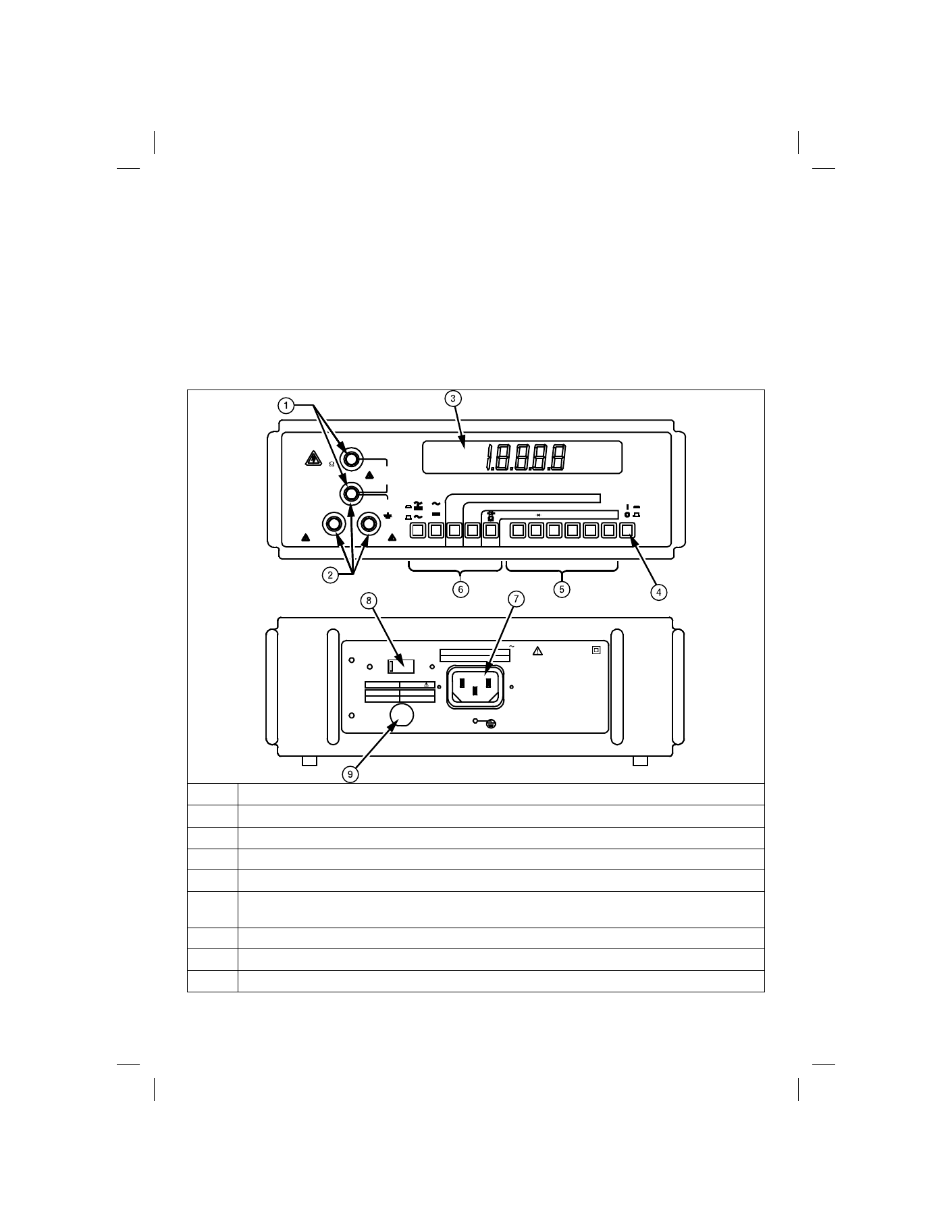
Voltage, Ohms, Diode and COM inputs.
B
Current (mA to 2A) and 20A inputs.
C
Reading display 0000 to 19999.
D
Power button (green).
E
Range selection switches. The pushbuttons are interlocked with the other ranges.
F
Function selection switches. The pushbuttons are interlocked with the other two white
function selection switches A and
Ω.
G
Line Power connector.
H
Line Voltage selector switch.
I
Line Power Fuse.
Figure 1: BDM40-UA Controls