Amprobe BDM40-UA Bench-Digital-Multimeter User Manual
Page 18
17
Cal Procedures
NOTE
To avoid contaminating the pcb with grease from the fingers, handle the pcb by its edges or wear gloves. If the
pcb does become contaminated, refer to the cleaning procedure given later in this section.
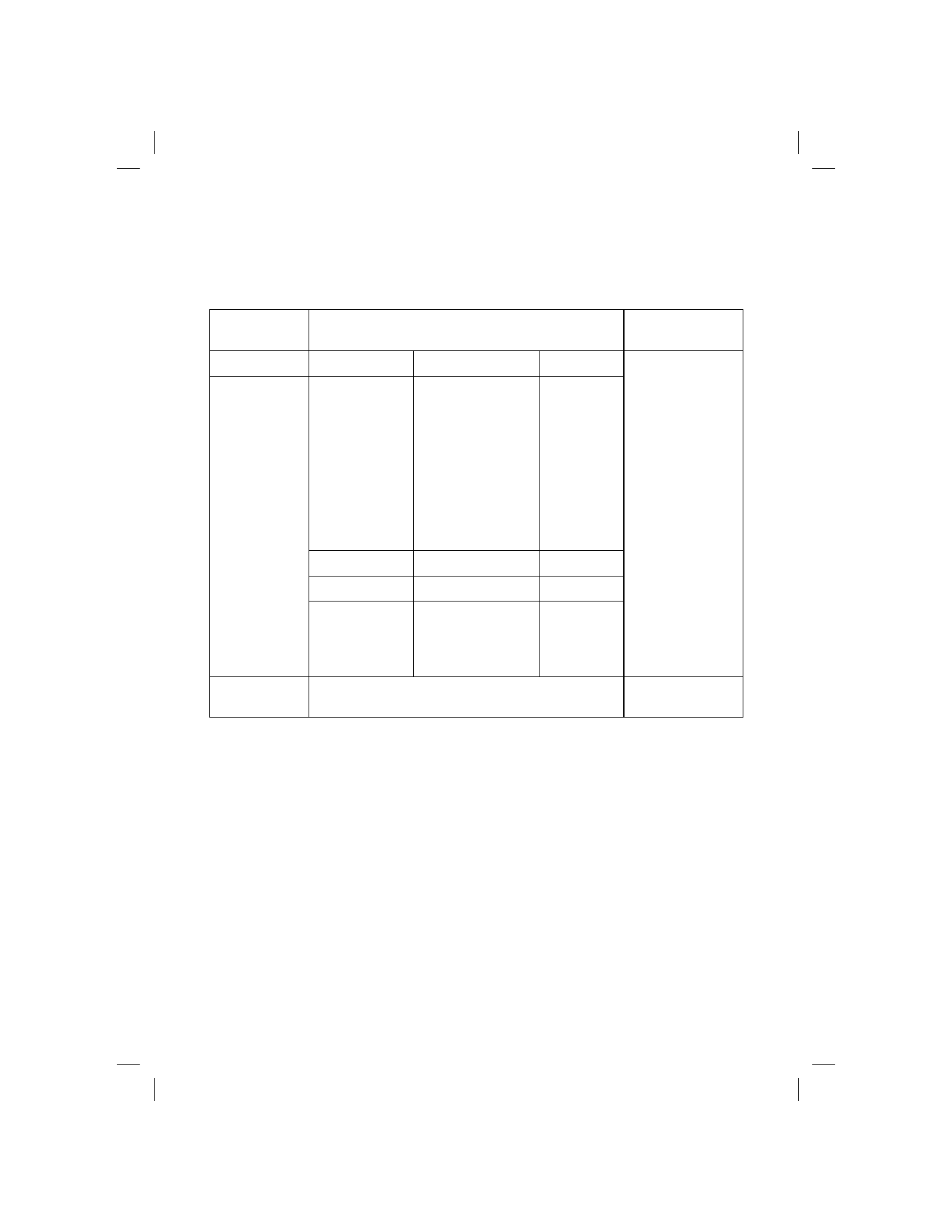
Table 3. Recommended Calibration
INSTRUMENT
TYPE
REQUIRED CHARACTERISTICS
RECOMMENDED
MODEL
Calibrator
DC Volts
0 to 1000V
± 0.006 %
AC Volts
100Hz
200Hz
1 kHz
10 kHz
20 kHz
50 kHz
0 to 750V
0 to 2V
0 to 750V
0 to 100V
0 to 100V
0 to 20V
± 0.06 %
± 0.06 %
± 0.06 %
± 0.06 %
± 0.1 %
± 0.5 %
DC Current
0 to 2000mA
± 0.05 %
AC Current
0 to 19mA, 100 Hz
± 0.1 %
Resistance
100
Ω, 1 kΩ
10 k
Ω, 100 kΩ
1M
Ω, 10MΩ
± 0.01 %
± 0.005 %
± 0.05 %
Fluke 5500
Calibration
Leads
24 “ shielded cable with a double banana plug at both ends
Pomona 2BC-24
Calibration Access
Use the following procedure to gain access to the calibration adjustments of this DMM.
1.
Set the POWER switch to the OFF position and remove the power cord plug from the receptacle in the
rear of the instrument.
2.
Remove the Phillips screw from the Bottom of your DMM.
3.
Grasp the front panel and slide the instrument out of the case.
4.
Turn the instrument upside down as viewed from the front panel.
5.
All adjustments necessary to complete the calibration procedure are now accessible.
6.
For reassembly, reverse the procedure (be careful to align the grooves in the sides of the front panel
with the guides located inside the case and to bend the flexible interconnect inwards and out of the
way).
Main PCB Access
Use the following procedure to gain access to all the components and test points ON THE MAIN PCB ASSEMBLY
FOR TROUBLESHOOTING AND REPAIRING.