Amprobe BDM40-UA Bench-Digital-Multimeter User Manual
Page 16
15
)
Scale
Full
Reading
x
(100
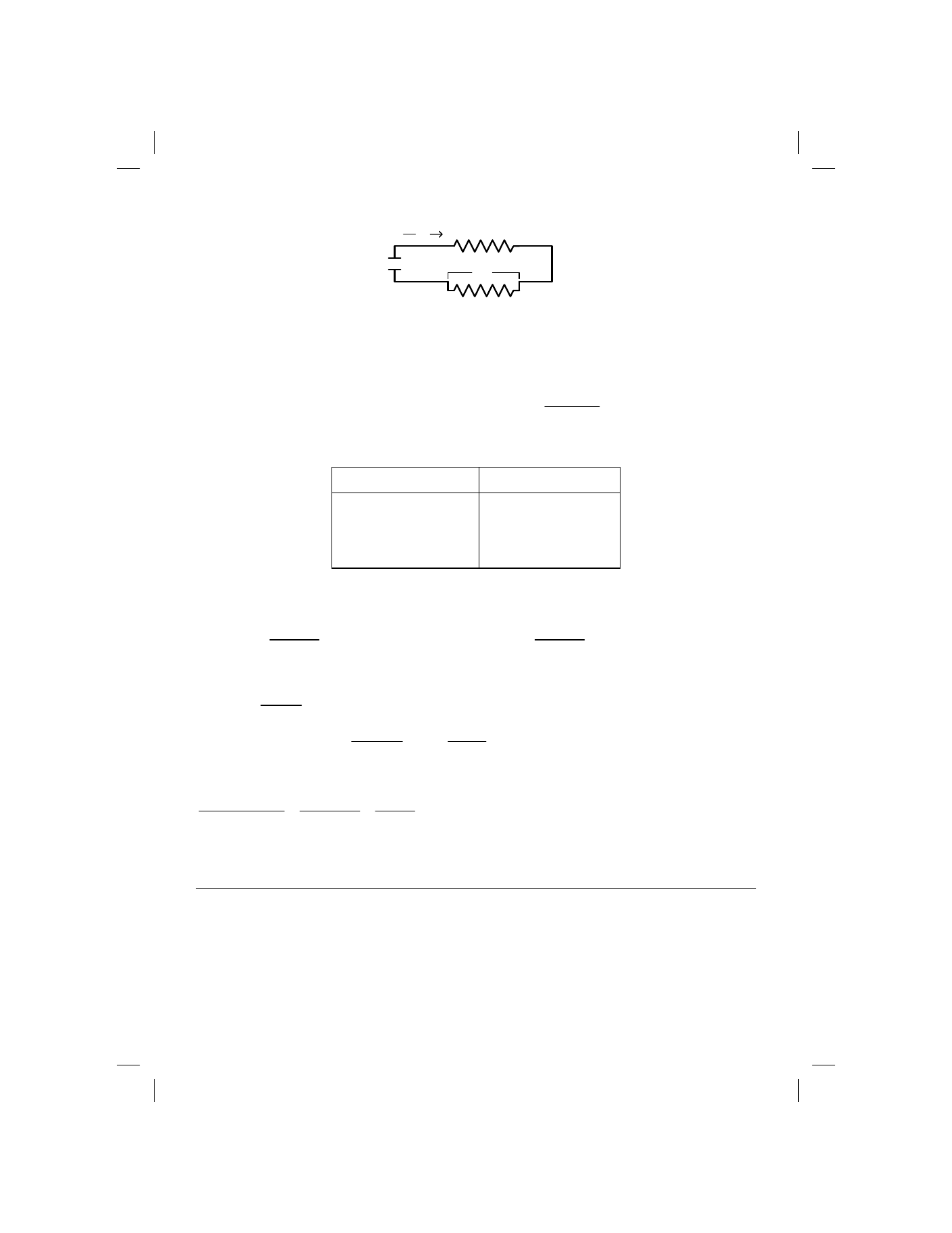
Calculating Burden Voltage Error
E
s
= Source voltage
R
L
= Load resistance + Source resistance
I
M
= Measured current (display reading in amps)
E
B
= Burden voltage (calculated) , i.e.,
Display reading expressed as a % of full scale
times full scale burden voltage for selected range. See table.
RANGE F.S.
BURDEN VOLTAGE
200µA to 200mA
2000mA
20A
0.3V max.
1V max.
2V max.
Maximum current error due to Burden Voltage
B
E
S
E
B
E
x
100
%
in
−
=
B
E
S
E
M
I
B
E
x
100
Amps
milli
in
−
−
=
Examples: Es = 14V, RL = 9
Ω, IM = 1497.mA,
0.749V
1.0
of
74.9%
x1.0
2000.0
1497.0
x
100
B
E
=
=
=
%
06
.
5
=
251
.
13
749
.
x
100
=
749
.
14
749
.
x
100
=
%
in
error
Maximum
Increase displayed current by 5.65% to obtain true current.
84.6mA
13.251
1121.2
.749
14
.749x1497
Amps
milli
in
error
Maximum
=
=
−
=
Increase displayed current by 84.6mA to obtain true current.
RESISTANCE MEASUREMENTS
The controls and terminals used to make resistance measurements are located on the front panel. The
measurement function is selected by pushing the k
Ω switch to the IN position. The colored area enclosing the kΩ
function switch extends up and to the right enclosing the six range values for the resistance function. To select a
particular resistance range, push the range switch immediately above the value to be measured. Connect the test
leads; red to the V-
Ω terminal and black to the COMMON terminal.
Use the following procedure to familiarize yourself with the resistance function and to see how the range switches
affect decimal point position on the LED.
E
S
R
L
I
M
E
B
AMMETER SHUNT