Amprobe BDM40-UA Bench-Digital-Multimeter User Manual
Page 14
13
Circuit loading error
Connecting most voltmeters to a circuit may change the operating voltage of the circuit if it loads the circuit down.
As long as the circuit resistance (source impedance) is small compared to the input impedance of the meter, the
error is not significant. For example, when measuring voltage with your meter, as long as the source impedance is
1 k
Ω or less, the error will be ≤ .01 %. If circuit loading does present a problem, the percentage of error can be
calculated using the appropriate formula in Figure 4.
Figure 4. Circuit Loading Error
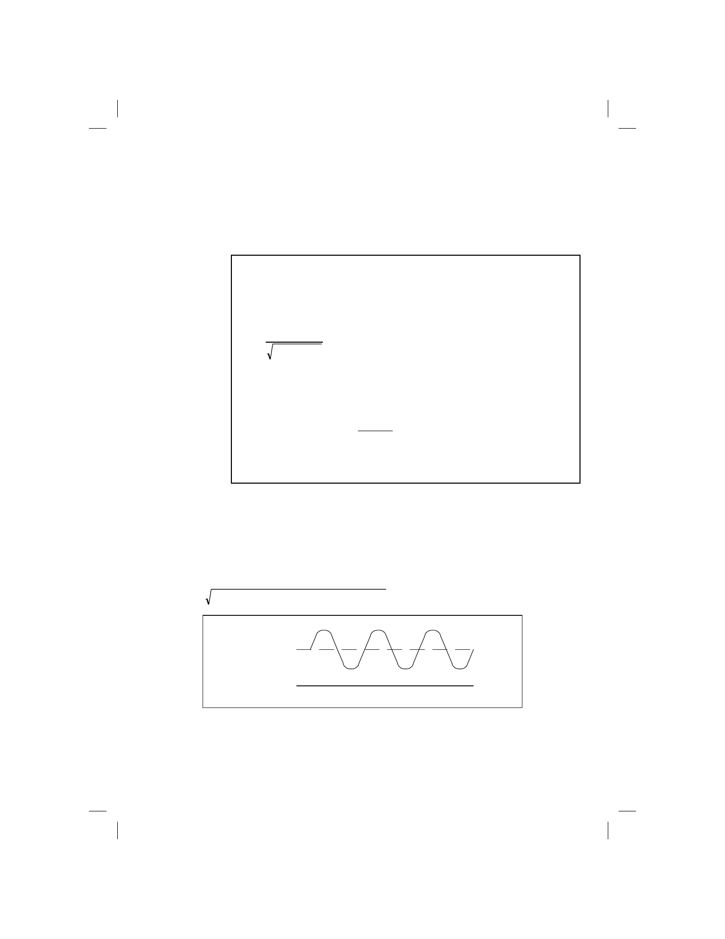
Combined AC and DC signal measurements
The waveform shown in Figure 5 is a simple example of an AC signal riding on a DC level. To measure waveforms
such as these, first measure the rms value of the AC component using the AC function of your meter. Measure
the DC component using the DC function of your instrument. The relationship between the total rms value of the
waveform and the AC component and the DC component is:
2
2
component)
(DC
rms)
component
(AC
Total
RMS
+
=
AC COMPONENT
DC LEVEL
OV
Figure 5. RMS Values
Insignificance of inherent meter offset
If you short the input of your meter while the AC voltage function is selected, you should have a reading of less
than 10 digits on the display. This small offset is caused by the action of amplifier noise and offset of the true rms
1. DC Voltage Measurements
Loading Error in % = 100 x Rs / (Rs + Rin)
Where: Rs = Source resistance in ohms of the circuit being measured.
Rin = Meter input resistance (1 x 10
7
ohms)
2. AC Voltage Measurements
First determine input impedance as follows:
2
7
)
FC
2
(
1
10
Zin
π
+
=
Where: Zin = effective input impedance
Rin = 10
7
ohms
Cin = 100 x 10
-12
Farads
F= Frequency in Hz
Then determine source loading error as follows:
Loading Error in % = 100 x
Zin
Zs
Zs
+
Where: Zs = Source impedance
Zin = input impedance
* Vector algebra required