Figure 3-10 formica writing surface and trim, 9 formica writing surface and trim, 10 cabinetry options – EFJohnson VR-CM50 User Manual
Page 32: 1 stabilizer kit (option 1)
CABINETRY ASSEMBLY FOR CRT CONSOLE SYSTEMS
3-6
February 1996
Part No. 004-3039-274
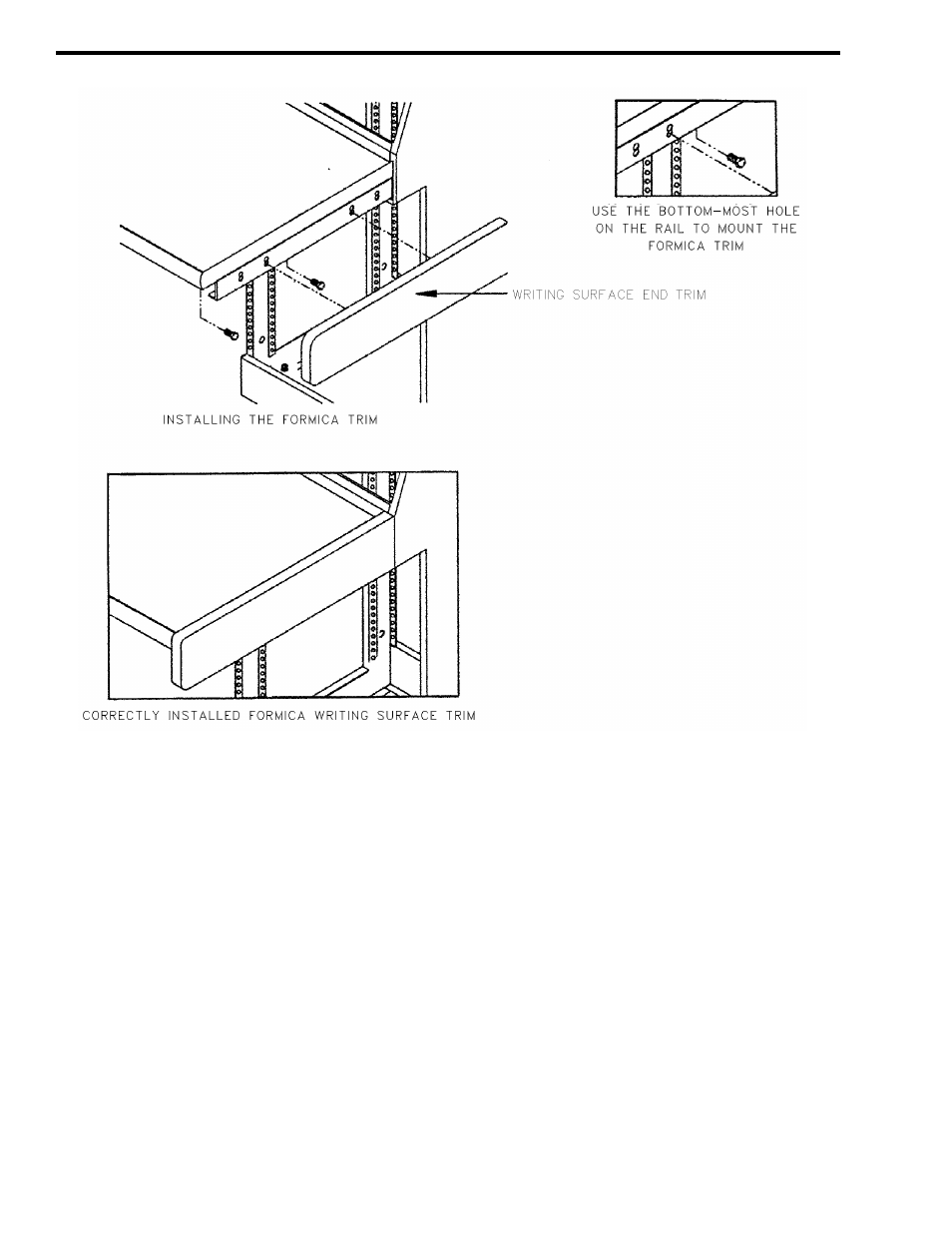
Figure 3-10 FORMICA WRITING SURFACE AND TRIM
Replace all keylocked enclosure panels. The
standard mechanical assembly is now complete. If
your console configuration has optional equipment,
PLEASE CONTINUE.
3.10 CABINETRY OPTIONS
VR-CM50 offers the following cabinetry options
for your system. Installation instructions begin in the
follow sections:
3.10.1 STABILIZER KIT (OPTION 1)
Refer to Figure 3-11. For cabinetry consisting of
two or more in-line cabinet bays, two (2) stabilizer
kits are required - one at each end of the console. For
3.9 FORMICA WRITING SURFACE AND TRIM
1. Align the Formica writing surface end trim with the
double holes in the last writing support rail. Use the
bottom-most hole, on the rail, to mount the Formica
writing surface end trim.
2. Fasten the Formica writing surface end trim using
the two (2) fender 1/4x1" washers and two (2) 8-
32x1/2 screws as shown in Figure 3-10.
3. A correctly mounted Formica writing surface end
trim is shown in Fig. 3-15. Notice that the bottom
of the end trim aligns perfectly with the console end
kit metal.