Pcc10w1, Model pcc10w1, Mounting – Whelen PCC10W1 User Manual
Page 2: Wiring
Page 2
BCKL
T
GND
G N D
POST
3A
Rear View
BANK 3
SWITCH OPTIONS
SWITCH OPTIONS
SWITCH OPTIONS
BCKL
T +V
+ V IN
SW 10 3A
SW 9
25A
SW 8
25A
SW 7
25A
+ V IN
SW 6
25A
SW 5
25A
SW 4
25A
+ V IN
SW3
25A
SW2
25A
SW1
25A
25A
25A
25A
25A
25A
25A
25A
25A
25A
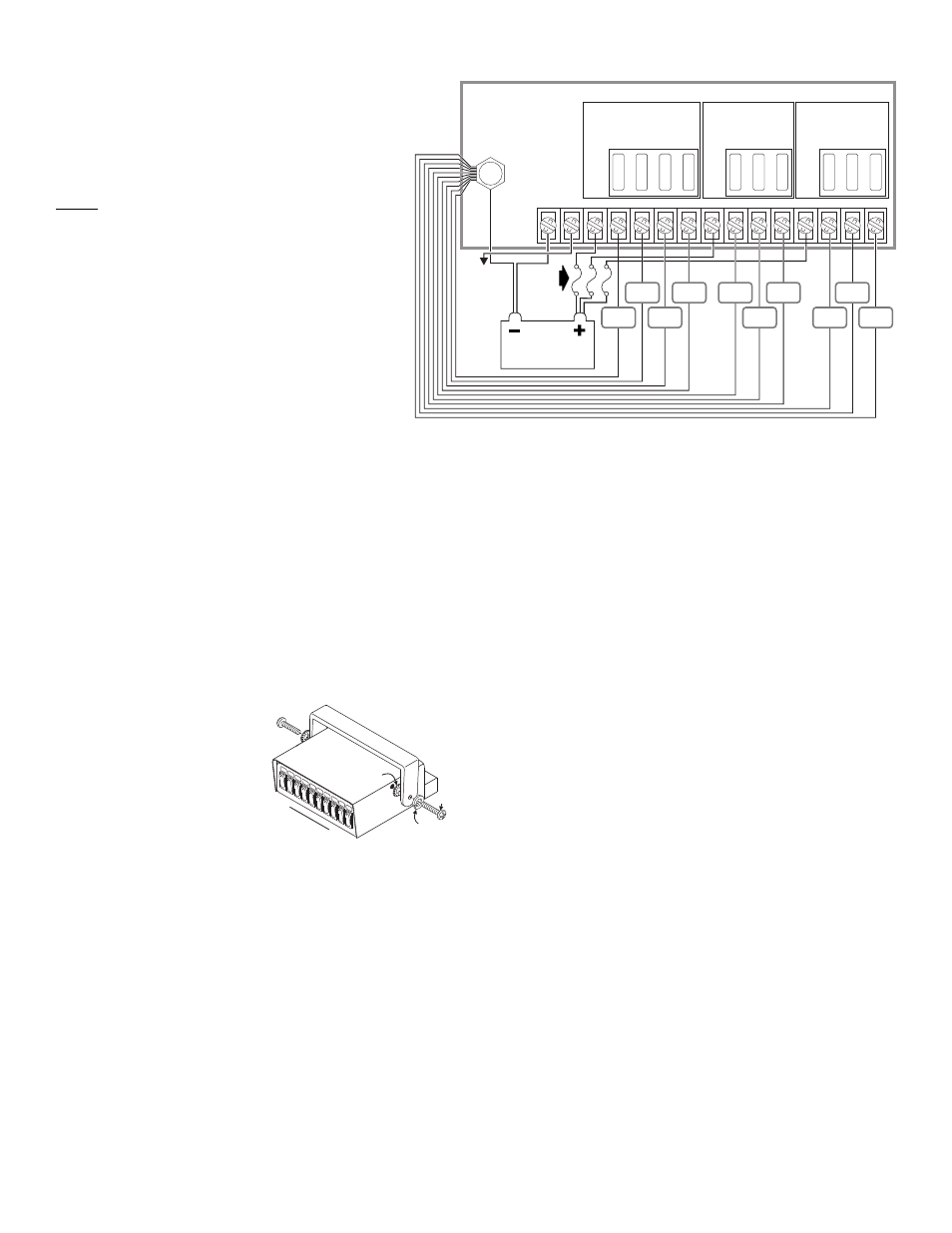
To +12 volt.
Ignition
activated
switch
Fuse @
30 AMPS
Each
(customer
supplied)
BATTERY
BANK 2
BANK 1
LOAD
LOAD
LOAD
LOAD
LOAD
LOAD
LOAD
LOAD
LOAD
LOAD
PCC10W1
W I R I N G
DIAGRAM
Split Lock
Washer
Screw
Ext. Tooth
Lock Washer
SW1
SW10
►
Model PCC10W1
WARNING! Nine of these switches are suitable for 25 amp, 12
volt DC applications. Any attempt to load these switches above
25 amps will result in switch failure. The momentary switch is
rated at 3 amps maximum.
WARNING!All customer supplied wires that connect to the
positive terminal of the battery must be sized to supply at
least 125% of the maximum operating current and be
FUSED at the battery to carry that load. DO NOT USE
CIRCUIT BREAKERS WITH THIS PRODUCT!
Congratulations on selecting the PCC10W ten switch power
control center. This product offers a unique and distinctive
collection of features. Features include:
•
Ignition controlled LED backlighting
•
Compact design
•
Switch 'active' LED indicators
•
Nine ON/OFF switches / One momentary switch
•
Three separate 'banks' of switches
•
A common Ground Post
•
72 switch function labels
Mounting:
An aftermarket center console is recommended for the mounting location
of the PCC10W1. This not only allows the driver to reach the controls
easily, but also keeps the unit safely out of the path of the vehicle’s SRS
air-bag. Follow the console manufacturer’s instructions for mounting
information. If a console-type mount is not possible, the PCC10W1
includes a bail strap mounting kit for over or under dash mounting.
WARNING: Regardless of the style selected, be sure to observe the
air-bag warning on the cover of this manual.
WARNING: Mounting this unit will require drilling. It is absolutely
necessary to make sure that no other vehicle components could be
damaged in the process. Check both sides of the mounting surface
before starting. If damage is likely, select a different location.
Bail Strap Mount:
1.
Position the bail strap in the
selected mounting location.
Using an awl or other suitable
tool, scribe the surface where
the mounting holes are to be
drilled.
2.
Carefully drill the mounting
holes in the areas scribed in
step one. The size of the drill
bit should be determined by
the size of the mounting hardware (customer supplied) and the
thickness of the mounting surface.
3.
Using the customer supplied mounting hardware, secure the bail
strap to the mounting location.
Console Mount:
Console manufacturers offer mounting kits that include all the necessary
hardware and brackets required to mount this unit into their console. The
console mount brackets are secured onto the unit the same way the bail
bracket is. Refer to the manual included with your console.
Function Labels: Take the supplied label kit and determine which label
describes the function of switch 1. Peel the label off the backing and place
it in the label window above switch 1 Press the label lightly into place.
Repeat for each switch.
Wiring:
BACKLT GND: This terminal supplies ground to both the units function
window backlighting and the switch 'active' LED indicators located on the
front of each switch. This terminal can be connected to any vehicle ground
that can supply 100ma.
BCKLT +V: This terminal supplies power to the units window backlighting.
This terminal can be connected to any ignition controlled +VBAT power
source that can supply 100ma.
GND POST: The ground post has been included as a convenient place to
terminate the switched loads return path to ground (See wiring diagram).
To prepare the post, Remove the provided ring terminal and attach it to a
10 AWG wire, now run this wire from the ground post to the negative post
of the battery. All of the loads return ground wires can now use the ground
post for termination using a spade or a ring terminal (customer supplied).
+V IN: There are three terminals labeled +V IN, each of these terminals
supply a bank of either 3 (bank 1 and 2) or 4 (bank 3) switches with their
power source. It is required for each of these terminals to be wired directly
to the positive post of the battery with a separate 14 AWG wire as shown
in the wiring diagram. Install a 30 amp fuse block (customer supplied) on
the end of each wire.
Note: Remove the fuse from the fuse block before connecting any
wires to the battery. Connect the fuse block wire to the POSITIVE (+) ter-
minal on the battery. There must not be more than 2 ft. of wire between the
fuse block and the battery. Since the wire between the fuse and battery is
“unprotected”, do not allow this wire to come in contact with other wires.
OPTIONAL WIRING FOR +V IN: Since each bank of switches have their
own individual power source (labeled +V IN), if there is a requirement for
some of the vehicles equipment to be switched to ground rather than
+Vbat, it is possible to wire one of the banks power inputs (labeled +V IN)
to the negative post of the battery and use the associated switches in that
bank to enable the ground activated devices. (Note: if the bank is used
for ground activation, the Switch 'active' LED indicators will not light for
any switch in that bank)
SW1-SW10: Connect these terminals to the desired equipment (loads) as
shown in the wiring diagram, be sure to use the proper wire size to handle
the current required to power the equipment.
IMPORTANT: It is the responsibility of the installation technician to
make sure that the installation and operation of this product will not
interfere with or compromise the operation or efficiency of any vehi-
cle equipment! Before returning the vehicle to active service, visu-
ally confirm the proper operation of this product.