Fig. 7, Fig. 8, Lighting control – Whelen WPA1 User Manual
Page 5: Wiring for the beta2, Control head, Fig. 9 rear view of pin housing, Fig. 6, Rear view ampseal connector (p2)
Page 5
BLUE
WHITE/BLACK
VIOLET
YELLOW
ORANGE
GRAY
BROWN
GREEN
WHITE
1
2
3
4
5
6
POSITION 1
9
8
7
Fig. 8
WPA Remote
Amplifier
WPA Control
Head
BLACK
/ WHITE
CONTROL
LINE
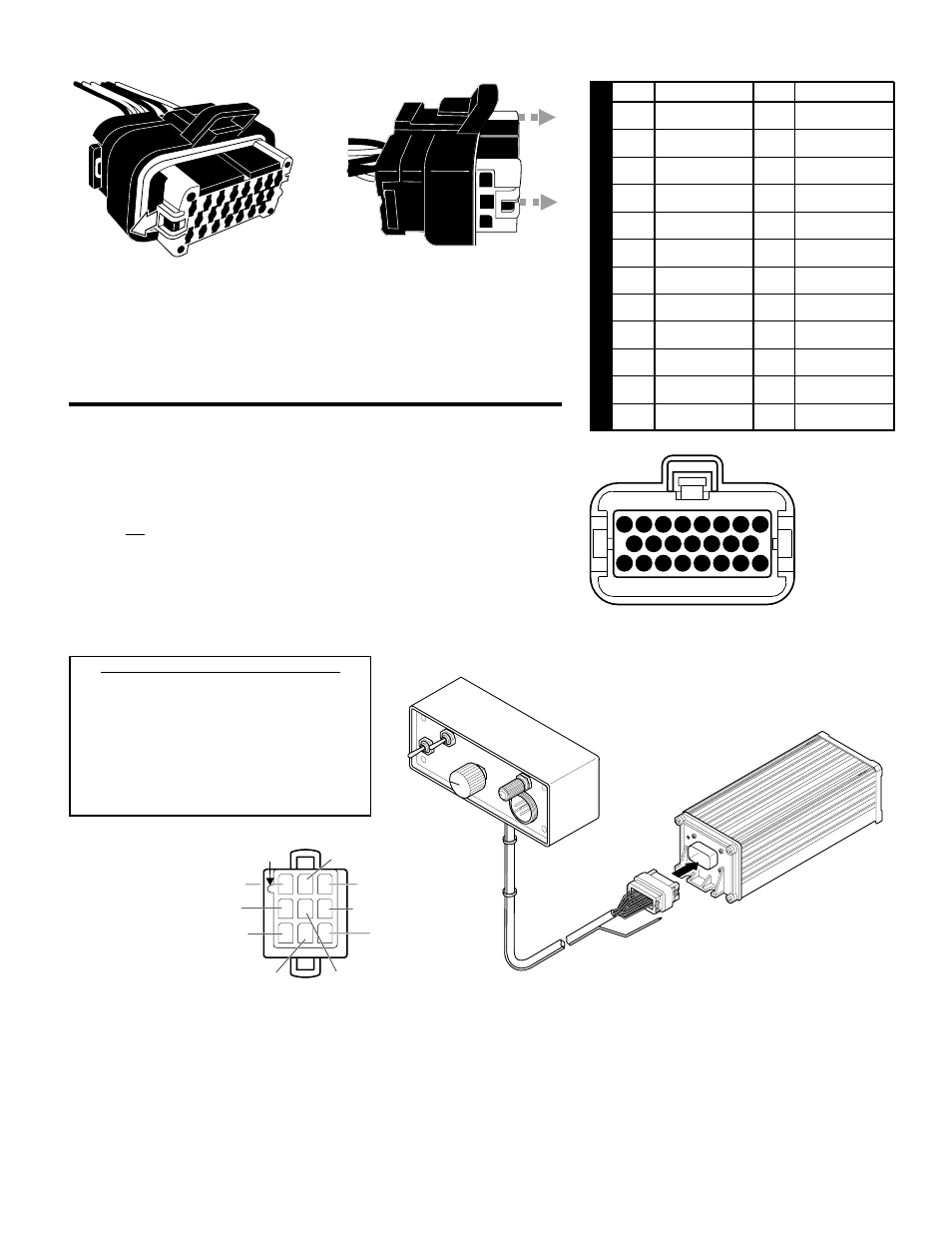
Lighting Control:
The WPA
TM
series control head offers a BLACK/WHITE
low-current control line that wire provides 12VDC / 250ma. This wire is activated
when the “Siren/Lights Siren” toggle switch on the control head is moved to the
“Lights Siren” position. In the “Siren” position this wire is disabled (Fig. 8).
Wiring for the BETA2
TM
Control Head:
The BETA2
Series Control
Head is not provided with the waterproof AMPSEAL plug connector. It is an
automotive application and has been designed for an automotive amplifier
(BETA112R). A 9-position female connector is provided with the
BETA2. After
routing the contact wires to the amplifier, take the 9-position female connector
and insert it into the 9-position male connector located on the BETA
amplifier
(see Fig. 9 below for 9-position wire details).
WPA CONTROL HEAD SPECIFICATIONS
INPUT VOLTAGE . . . . . . . . . . 10 to 32 VOLTS
INPUT CURRENT (OFF) . . . . . 0 mA
INPUT CURRENT . . . . . . . . . 500mA (MAX.)
OUTPUT VOLTAGE . . . . . . . . INPUT VOLTAGE -1.4V
OUTPUT CURRENT . . . . . . . . 500mA (MAX.)
OPERATING TEMP. . . . . . . . . -30° C. to +60° C.
OPERATING HUMIDITY . . . . . 100% NON-CONDENSING
OPERATING SHORT PROT.. . 500mA POLY FUSE
Fig. 9
Rear View
of Pin Housing
The installation of your control head will be complete after the fuse block wire of the remote amplifier is connected to the POSITIVE
(+) terminal of the battery. After this connection has been made, inspect the fuses of the amplifier and at the battery. If either of these
fuses is blown, carefully inspect all of the circuit wires and make sure they are wired correctly. Replace the blown fuses with ones of
an identical amp rating. If these fuses blow after installation or activation, contact Whelen Engineering Technical Support.
Bend Ears
Outward
Fig. 6
Slide Out
Center
Fig. 7
Rear View
Ampseal
Connector
(P2)
PIN
12
11
10
9
8
7
6
5
4
3
2
1
13
14
15
16
17
18
19
20
21
22
23
PIN
COLOR
BROWN FROM
CONTROL HEAD
YELLOW FROM
CONTROL HEAD
VIOLET FROM
CONTROL HEAD
BLUE FROM
CONTROL HEAD
N/C
GREEN FROM
CONTROL HEAD
ORANGE FROM
CONTROL HEAD
GRAY FROM
CONTROL HEAD
WHT/BLK FROM
CONTROL HEAD
WHITE FROM
CONTROL HEAD
COLOR
N/C
N/C
BLUE
BLACK
INLINE
FUSE HOLDER
ORANGE
BLUE
BROWN
N/C
N/C
N/C
N/C
N/C
Ta
bl
e1/
Ampseal
W
iring
Chart
23
22
21
20
19
18
17
16
9 10 11 12 13 14 15
1 2 3 4 5 6 7 8
Before the wires can be inserted into their sockets, you must first release the
Internal Wedge Lock. To do this you must bend both ears out slightly, while at
the same time, sliding the center piece (shown in white) out no more than 1/4”.
This will release the internal wedge lock. After inserting the wires, slide the
center piece back in to close the internal wedge lock. NOTE: Be careful not to
bend the ears too far out as they might break off.