Abs sensor replacement, Abs sensor replacement procedure, Axle alignment inspection – SAF-HOLLAND XL-TA10006OM Drum Brake Axles Tapered and Parallel Spindle Axles User Manual
Page 27
27
XL-TA10006OM-en-US Rev B · 2014-03-13 · Amendments and Errors Reserved · © SAF-HOLLAND, Inc., SAF-HOLLAND, HOLLAND, SAF,
and logos are trademarks of SAF-HOLLAND S.A., SAF-HOLLAND GmbH, and SAF-HOLLAND, Inc.
ABS Sensor Replacement
Figure 51
Figure 53
Figure 52
18. ABS Sensor Replacement Procedure
18.1 Sensor Removal
NOTE: ABS sensors MUST match the system. DO NOT mix
sensors from different manufacturers.
1. Manually release the brakes.
2. Remove brake drum assembly as described in Section 4.
3. Disconnect the ABS sensor connector and remove the
sensor from the sensor holder by pulling straight out
(Figure 51).
4. Remove the sensor retaining spring clip, if necessary.
18.2 Sensor Installation
NOTE: Be sure to use the correct spring clip for the sensor
being installed.
1. Install the sensor retaining spring clip, if removed, into
the sensor holder.
2. Install the ABS sensor into the spring clip and sensor
holder. Push the sensor in until it contacts the tone ring
(Figure 52).
3. Connect the ABS sensor connector.
4. Re-install drum using support device such as a drum dolly
jack (Figure 37).
5. Adjust brakes as described in Section 17.
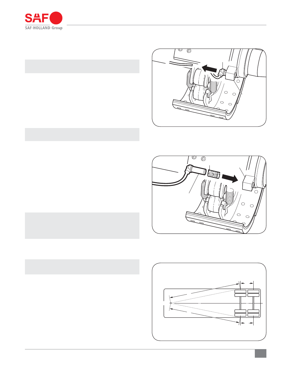
19. Axle Alignment Inspection
NOTE: Alignment can be achieved using an optical device
designed specifically for this purpose. Follow
the instructions in the optical device operating
instructions to align the axles.
1. To manually align the axles attached to your trailer, first
pull the trailer in a straight line for a sufficient distance
to release/clear any binds in the suspension.
NOTE: A straight, unbound suspension is the position of
a suspension during normal operations.
Using the alignment procedures per the suspension
manufactuer’s recommendations, align the axles to the
following specifications.
2. Measure the distance from the king pin to the centerline
of the spindles on each side of the front axle. Dimensions
A and B MUST be equal to within 1/8" (4 mm) (Figure
53, A and B).
3. Measure the distance from the centerline of the spindles
of the front axle to the centerline of the spindles of each
additional axle. Dimension C and D must be equal to
within 1/16" (1 mm) (Figure 53, C and D).
ABS SENSOR
CONNECTOR
ABS SENSOR
CONNECTOR
SPRING CLIP
KING PIN
A=B
A
D
C
B
C=D
ABS SENSOR
HOLDER
ABS SENSOR
HOLDER