Hubs, bearings, and seal components – SAF-HOLLAND XL-TA10006OM Drum Brake Axles Tapered and Parallel Spindle Axles User Manual
Page 14
14
XL-TA10006OM-en-US Rev B · 2014-03-13 · Amendments and Errors Reserved · © SAF-HOLLAND, Inc., SAF-HOLLAND, HOLLAND, SAF,
and logos are trademarks of SAF-HOLLAND S.A., SAF-HOLLAND GmbH, and SAF-HOLLAND, Inc.
Hubs, Bearings, and Seal Components
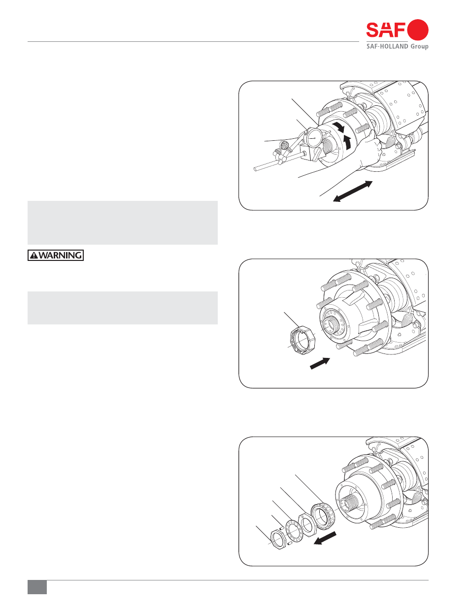
8. Check the wheel bearing end play as follows:
a. Attach the magnetic base of a dial indicator to
spindle. Touch dial indicator stem to hubcap gasket
face (Figure 17).
b. Reading Number One – Slightly rotate wheel-end
in both directions while pushing inward until dial
indicator does not change. Set the dial indicator to
zero (Figure 17).
c. Reading Number Two − Slightly rotate hub in both
directions while pulling outward until dial indicator
does not change (Figure 17).
d. End play is the difference between reading number
one and reading number two.
IMPORTANT: Final adjustment should allow the wheel to
rotate freely with 0.001" to 0.005" (0.025
mm to 0.0127 mm) end play. If end play is not
within specification, re-adjustment is required.
Failure to maintain proper hub bearing
adjustment could allow bearing failure
and wheel-end separation which, if not
avoided, could result in death or serious injury.
NOTE: If wheel bearing end play needs adjustment,
remove outer nut and lock washer. Tighten or
loosen inner nut as needed. Return to Step 6.
9. Install
set screw into an accessible threaded hole in the
lock washer. Set screw MUST contact the inner adjusting
nut. Tighten to 16-20 in.-lbs. (1.8-2.2 N•m) (Figure 19).
7.2. Hub Bearing Adjustment
Using Pro-Torq
®
Axle Nut
The unit could be equipped with a Pro-Torq
®
spindle nut
(Figure 18). Refer to Stemco
®
“Pro-Torq
®
Installation
Instructions” (Part No. 09-571-006) which can be found
at www.stemco.com for more information.
HUB ASSEMBLY
DIAL INDICATOR
Figure 17
Figure 18
PRO-TORQ®
SPINDLE NUT
Figure 19
AXLE WASHER
INNER AXLE NUT
SET SCREWS
OUTER HUB BEARING
3-PIECE SPINDLE NUT SHOWN
AXLE NUT