Brake adjuster replacement, Brake adjuster removal, Brake adjuster installation – SAF-HOLLAND XL-TA10006OM Drum Brake Axles Tapered and Parallel Spindle Axles User Manual
Page 22
22
XL-TA10006OM-en-US Rev B · 2014-03-13 · Amendments and Errors Reserved · © SAF-HOLLAND, Inc., SAF-HOLLAND, HOLLAND, SAF,
and logos are trademarks of SAF-HOLLAND S.A., SAF-HOLLAND GmbH, and SAF-HOLLAND, Inc.
Brake Adjuster Replacement
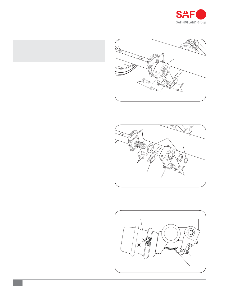
Figure 38
Figure 40
Figure 39
13. Brake Adjuster Removal
NOTE: Maintenance procedures in this section require
re-positioning of the brake adjuster. Consult the
manufacturer’s manual for procedures to properly
operate brake adjusters.
1. Remove the cotter pins that secure the brake adjuster/brake
chamber clevis pins (Figure 38). Remove the clevis pins.
2. Remove the retaining ring and washer that secure the
brake adjuster to the S-Camshaft (Figure 39).
3. Remove the self-adjusting brake adjuster from the spline
end of the brake S-Camshaft.
4. Rotate adjusting mechanism to back the brake adjuster
out of the clevis in accordance with brake adjusters
manual.
14. Brake Adjuster Installation
1. Apply an even coat of anti-seize compound to splined
surface of S-Camshaft.
2. Position the spacing washers on both sides of the brake
adjuster, then install the brake adjuster onto the S-Camshaft
spline and secure the brake adjuster on the S-Camshaft
by assembling the retaining ring (Figure 40).
3. Align the brake adjuster to the clevis and pin together
using the clevis pins and cotter pins (Figure 38).
4. Apply service and spring brake several times. Final
brake adjustment is required to ensure proper initial
brake operation. The brake adjuster will then seek
the proper working stroke during normal operating
conditions. Refer to brake adjuster and brake chamber
manufacturers' procedures for proper adjustment.
CLEVIS
PUSH ROD
JAM NUT
BRAKE ADJUSTMENT NUT
BRAKE CHAMBER
CLEVIS PINS
COTTER PINS
BRAKE ADJUSTER
SPACING WASHERS
BRAKE ADJUSTER
CLEVIS
CLEVIS PINS
S-CAM SPLINE
COTTER PINS
RETAINING RING