Installation, Input connections, Load connections – KEPCO KLP Series Quick Start Guide, P/N 228-1616, Rev 2 User Manual
Page 5: Input connections load connections
102607
228-1616 REV 2
5
KEPCO, INC. " 131-38 SANFORD AVENUE " FLUSHING, NY. 11355 U.S.A. " TEL (718) 461-7000 " FAX (718) 767-1102
http://www.kepcopower.com " email: [email protected]
INSTALLATION.
Install units in a 19 inch-wide rack. Optional slides may be used. Leave the front
and rear panels clear of obstructions to ensure adequate cooling. For parallel, series and master-slave
configurations, refer to the User Manual.
INPUT CONNECTIONS. Wire the mating source power connector provided (142-0381) for your input
mains (see Table 5 for mains voltage range). The user must provide a properly sized and rated mains
lead (line cord) and service with a current rating compatible with the anticipated input current. Line cords
available as accessories are listed in Table 3. Plug the source power connector into the source power
inlet connector at the rear panel.
LOAD CONNECTIONS. Connect the load to the (+) and (–) DC OUTPUT terminals on the rear panel
(Figure 2). (+M) and (–M) outputs are for connection of external monitoring equipment such as a DVM,
oscilloscope, etc.
Configuration of local sensing is facilitated by pre-installed jumpers which configure the unit for local
sensing.as shown in Figure 2.
NOTE: Output Sense lines must be connected for proper operation, either locally, or at the load
(remote).
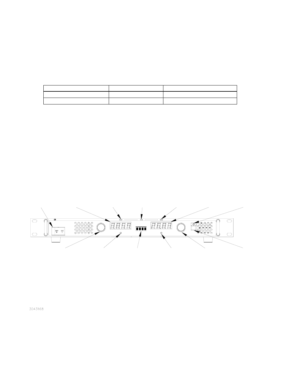
FIGURE 1. KLP SERIES, FRONT PANEL CONTROLS AND INDICATORS
TABLE 5. INPUT CURRENT SERVICE RATING AND CONDUCTOR SIZES
MAINS VOLTAGE RANGE
CURRENT SERVICE RATING
CONDUCTOR SIZE
100 - 132V a-c, 50/60Hz
20 Amp
#12AWG [2,0 mm²]
180 - 265V a-c, 50/60Hz
15 Amp
#14AWG [3,0 mm²]
POWER ON/OFF
Turns unit on/off.
Circuit Breaker
gives input
protection.
VOLTAGE
control/momentary
switch
Rotate to set
output voltage.
Tap to enter
SETPOINT mode.
(Also used for
other functions.)
DC VOLTS
Display shows
output voltage or
voltage setpoint.
(Also used for
special functions).
CV
indicator lights
green when
operating in
constant voltage
mode
Status
Display normally
blank. Shows
active function or
blinks for error
messages.
CC
indicator lights
amber when
operating in
constant current
mode
DC AMPERES
display shows
actual output
current or
current set point
(Also used for
special functions.)
CURRENT
control/momentary
switch
Rotate to set
output current.
Tap to enter
SETPOINT mode.
(Also used for
other functions.)
DC OUTPUT
indicator lights
green to show
output enabled
DC OUTPUT
on/off switch
enables or
disables output.
(Also used to
accept front panel
inputs.)
PROTECT
momentary switch
Used to set
overvoltage and
overcurrent
protection limits.
Requires a thin
tool (e.g., end of
paper clip) to
press switch.
LAN
indicator
lights green
when LAN
interface is
in use
[-1.2K Models]
FUNCTION
momentary switch
Used to access
calibration,
GPIB address,
RS232 baud rate
(-1200 Models),
Virtual Model and
Utility functions.
Requires a thin
tool (e.g., end of
paper clip) to
press switch.