Receiver jumpers, Setting jmp1 for rs-232 communication – Extron electronic MTP U R RS SEQ User Manual
Page 9
MTP U R Series • Introduction
5
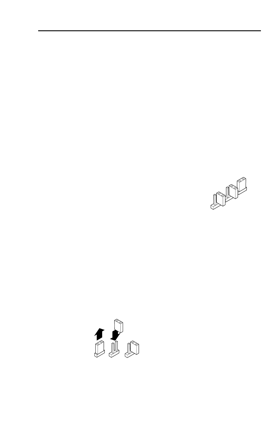
JMP1
JMP3
JMP2
Default settings as
viewed from rear
N
The transmitter and receiver are designed for and
perform best with Extron Enhanced Skew-Free A/V cable
terminated in accordance with the TIA/EIA T 568 A
wiring standard. CAT 5 cables are acceptable but less
preferable. We also recommend the use of pre-terminated
and tested cables. Cables terminated on site should
be tested before use to ensure that they comply with
Category 5/5e/6 specifications.
The recommendations shown in the table apply for a
single transmitter and receiver. For example, the
maximum suggested range for 1024 x 768 video is 300’
(90 m) with Pre-Peak off and 600’ (150 m) with it on.
Receiver Jumpers
The MTP U R receivers have three jumpers on the main board.
Jumper 1 (JMP1) controls RS-232 directional communication,
and Jumpers 2 (JMP2) and 3 (JMP3) control vertical and
horizontal sync respectively.
By default, JMP1 is closed on all models and
configured to send serial data both ways
(bidirectional), transmitter-to-receiver and
receiver-to-transmitter. Jumpers 2 and 3 are
open (negative sync) by default.
Setting JMP1 for RS-232 communication
Jumper 1 can be repositioned to enable unidirectional
communication as follows:
1
.
If applicable, disconnect all cables, remove the receiver
from its installation location, and remove any mounting
brackets installed.
2
.
Remove the two screws from either side of the receiver
(four screws total) and lift the top cover off of the receiver.
3
.
Locate jumper JMP1 on the main board. Remove and
reposition it over one pin (see figure 3).
Reposition the jumper
block to cover one pin.
Figure 3 — Setting jumper 1 to uni-directional
4
.
Put the top cover back into place.
5
.
Reinstall the four screws removed in step 2. If any
mounting brackets were removed in step 1, put them back
into position as you reinstall the screws