Operation – Sealey VS1830 User Manual
Page 2
NOTE: It is our policy to continually improve products and as such we reserve the right to alter data, specifications and component parts without prior notice.
IMPORTANT: No liability is accepted for incorrect use of this product.
WARRANTY: Guarantee is 12 months from purchase date, proof of which will be required for any claim.
INFORMATION: For a copy of our latest catalogue and promotions call us on 01284 757525 and leave your full name and address, including postcode.
01284 757500
01284 703534
Sole UK Distributor, Sealey Group,
Kempson Way, Suffolk Business Park
,
Bury St. Edmunds, Suffolk,
IP32 7AR
www.sealey.co.uk
Original Language Version
VS1830.V2 Issue: 1 - 13/01/14
3. OPERATION
3.1 If fitted, remove the circlips from either side of the
piston gudgeon pin (Fig.1).
3.2 Unscrew clockwise and remove the dies from the
threaded rod shown in Fig.2.
3.3 Lubricate the M12 portion of the threaded rod with
a silicone grease or similar product.
3.4 Ensure the threaded rod is fully wound clockwise into
the main body (Fig.2), up to the hexagon shoulder.
3.5 Select the required adaptor and locate as indicated
inside the main body in Fig.2. The full skirt adaptor
has a radiussed concave face and this should be
orientated so it fits “flush” against the piston shown in
Fig.3. The short skirt adaptor is designed with a flat
face for “waisted” slipper pistons.
3.6 Choose the die that is the closest fit to the gudgeon
pin outside diameter.
3.7 Screw the die anticlockwise on to the threaded rod;
the die must be a minimum distance of L + 2mm from
the end, see Fig.2.
3.8 Screw the knurled locknut anticlockwise on to the
threaded rod until tight against the die, see Fig.3.
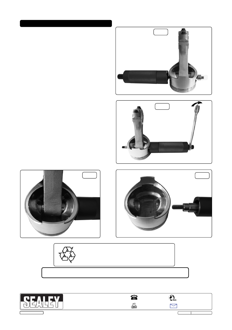
3.9 When you are sure that the die is central on the
gudgeon pin, proceed using a 14mm spanner, turn
the threaded rod anti-clockwise (Fig.4) to start
extracting the gudgeon pin.
3.10 The gudgeon pin will start to draw through the piston
(Fig.5). If the threaded rod nut requires excessive
force stop and check for obstructions, make sure the
die is central and that all circlips have been removed.
3.11 Finally remove the tool from the piston with the
gudgeon pin attached (Fig.6).
3.12 Unscrew the knurled locknut and remove the die and
gudgeon pin.
3.13 Wipe clean all the remover components with a dry
cloth and return to plastic wallet.
© Jack Sealey Limited
Fig.6
Fig.5
Fig.4
Fig.1
Fig.3
Environmental Protection.
Recycle unwanted materials instead of disposing of them as
waste. All tools, accessories and packaging should be sorted,
taken to a recycle centre and disposed of in a manner which
is compatible with the environment.
Parts support is available for this product. To obtain a parts listing and/or diagram,
please log on to www.sealey.co.uk, email [email protected] or telephone 01284 757500.
Ensure the axis of the threaded
rod shares the same axis of the
gudgeon pin (concentricity).