Fig.1, Fig.3 fig.2, Introduction & specifications – Sealey PH250 User Manual
Page 2: Mounting, Operation
2. INTRODUCTION & SPECIFICATIONS
Approved to EU and UK Lifting Gear Regulations. These hoists are intended for use where
a suitable support facility exists. Support brackets are included with the equipment.
The support bar is not included.
Specifications . . . . . . . . PH250.V4 . . . . . PH400.V3
Lifting capacity: single line . . .125kg . . . . . . . . .200kg
double line . . .250kg . . . . . . . . .400kg
Lift height:
single line . . . 12mtr . . . . . . . . . 12mtr
double line . . . . 6mtr . . . . . . . . . . 6mtr
Cable diameter: . . . . . . . . . . . 3.0mm . . . . . . . . 3.8mm
Rated Speed (Max):. . . . . . 8mtr/min . . . . . . .8mtr/min
Motor:
. . . . . . . 230V/500W . . . . 230V/750W
Weight:
. . . . . . . . . . . 10.5kg . . . . . . . . . .16kg
3. MOUNTING
3.1.
Unpack the hoist and check contents against the items listed below. Should
there be any damaged or missing parts contact your supplier immediately.
Contents
1. Hoist assembly.
2. Double line pulley and hook (loosely assembled).
3. Four each of: bolts, spring washers and washers.
4. Two mounting brackets.
3.2.
Ensure that the selected hoist support is sufficiently strong and will also hold
the hoist in a horizontal position. If alternative mounting brackets are
fabricated, ensure that these are at least as strong as those provided, and
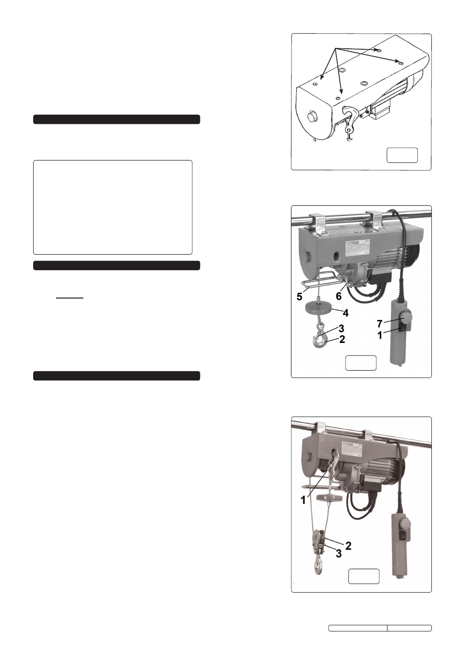
align with the mounting holes (fig.1.A) in the hoist.
4. OPERATION
fig.1
WARNING! Before using the hoist ensure that you have read, understood
and apply the safety instructions in Section 1.
IMPORTANT: In an emergency press the emergency stop button to halt the
hoist (fig.2.7), to release the emergency stop button, turn it clockwise.
4.1. Ensure that the load to be lifted is directly below the hoist and that any lifting
straps, ropes or chains being used are capable of supporting the weight.
4.2.
With mains power switched on, operate control switch (fig.2.1) to bring hook to
load height. Press lower half of switch to lower hook and upper half to raise
hook. Release switch to stop hoist.
4.3.
Attach hoist hook (fig.2.2) to load, ensuring that safety bar (fig.2.3) is fully
closed.
4.4.
Use control switch (fig.2.1) to raise or lower the load to the required height.
4.5.
To carry out a double line lift, first hook the single line hook in aperture in hoist
frame (fig.3.1). Then take double line pulley and hook (fig.3.2), remove 'R' pin,
shaft and washers and undo nyloc nuts and remove small bolts (fig.3.3).
Place pulley on cable loop between hoist drum and single line hook. Replace
hook and refit shaft, washers and 'R' pin, then refit small bolts and tighten the
nyloc nuts on them. Ensure that pulley is free to rotate. Proceed as above in
4.1. to 4.4.
Notes: 1. It is important not to completely empty the cable drum, it is designed so
that if the cable is run out to it's end, the cable will engage with the safety
bar (fig.2.6) and cut the motor out, and there will still be sufficient
windings on the drum. If however the cable is being pulled out of the hoist
at an angle, it may not engage with the safety bar, so caution is needed in
this situation.
2. In order to prevent the motor/gearbox from overheating, the hoist
should not be operated for longer than four minutes at any one time. Any
period of use should be followed by a similar period with the hoist at rest.
3. Do not wind loose cable onto drum - ensure that cable is always under
tension.
DO NOT use more than one hoist to lift a load.
DO NOT leave the hoist unattended with a suspended load.
DO NOT wrap the hoist cable around the load.
DO NOT use the hoist to lift dangerous materials.
DO NOT use the hoist to lift people.
Use a qualified person to lubricate and maintain the hoist.
When not in use and before carrying out repairs/maintenance isolate the hoist from the
power supply.
DANGER! Ensure that personnel are prevented from passing beneath the hoist and load.
A
PH250.V4 & PH400.V3 Issue: 1 - 04/03/10
Original Language Version
fig.3
fig.2