Sealey AK458DX User Manual
Page 2
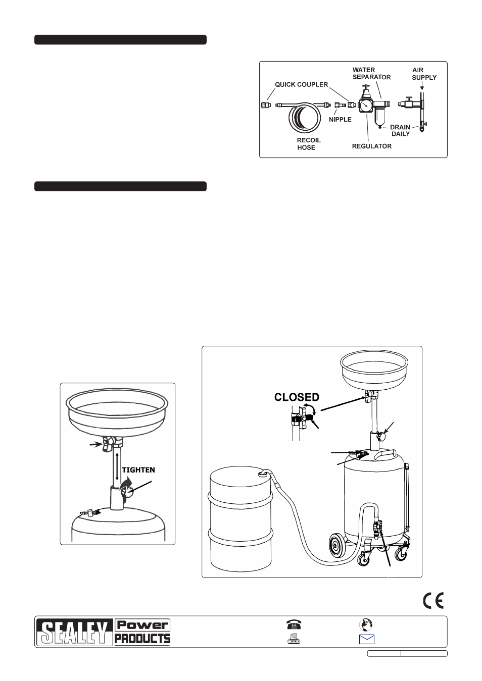
the recommended hook-up is shown in fig.4.
4.1.
Ensure the air valve is in the "off" position before connecting to the
air supply.
4.2.
You will require an air pressure of 0.45bar (7psi).
WarninG! Ensure the air supply is clean and does not exceed
pressures specified in these Instructions. too high an air
pressure and/or unclean air will shorten the drainer life due to
excessive wear, and may be dangerous, causing damage and/or
personal injury.
4.3.
Drain the air tank daily. Water in the air line may damage the drainer.
4.4.
clean the air inlet filter screen weekly.
4.5.
Line pressure should be increased to compensate for unusually
long air hoses (over 8 metres). the minimum hose diameter should
be 10mm I.D. and fittings must have the same inside dimensions.
4.6.
Keep hose away from heat, oil and sharp edges. check hoses for
wear, and make certain that all connections are secure.
4. air SUPPlY
fig.4
5. oPeraTion
1
2
fig.5
WarninG! ensure that you read, understand and apply the safety instructions in Section 1.
5.1.
5.1.1. to raise or lower the drain pan, slacken off the handwheel (fig.5.1) while supporting the weight of the drain pan, move drain pan to
the correct height and then tighten the hand wheel.
Note! Oil should be removed when hot (70-80°C). Keep hands, face and body protected using suitable personal protective
equipment (PPE).
5.1.2. Drain the oil into the drain pan ensuring that the drain pan valve is open (fig.5.2) and the ball valve tap at the base of the tank is
closed (fig.3.1).
5.1.3. When draining is complete, lower oil pan before moving drainer.
WarninG! ensure the oil level never rises above the maximum level on the indicator located on the side of the tank.
5.2.
emptying
5.2.1. Ensure that drain pan valve (fig.6.2) is closed and hand wheel (fig.6.1) is tight.
5.2.2. Attach the end of the drain hose to a suitable waste oil container (fig.6).
5.2.3. open ball valve tap (fig.6.5).
5.2.4. connect air supply at a pressure of 0.45bar to coupling (fig.6.4) and open valve 3 (fig.6.3).
5.2.5. After the fluids have been transferred from the tank close valve 5 (fig.6.5).
5.2.6. Disconnect from air supply and vent any pressure remaining in the tank by opening drain pan valve (fig 6.2) and/or air valve
(fig.6.3.).
Note! This unit is equipped with a safety valve that has been factory set to cut in at a maximum of 0.45bar (7psi).
1
2
3
4
5
fig.6
NOTE: It is our policy to continually improve products and as such we reserve the right to alter data, specifications and component parts without prior notice.
iMPorTanT: no liability is accepted for incorrect use of this product.
WarranTY: Guarantee is 12 months from purchase date, proof of which will be required for any claim.
inForMaTion: for a copy of our latest catalogue and promotions call us on 01284 757525 and leave your full name and address, including postcode.
01284 757500
01284 703534
Sole UK distributor, Sealey Group,
Kempson Way, suffolk Business Park
,
Bury st. Edmunds, suffolk,
IP32 7Ar
www.sealey.co.uk
Web
Original Language Version
AK458DX.V4 Issue: 2 - 09/07/12