Fig.13, Fig.14, I"/"o"/"ii – Sealey IR55 User Manual
Page 6: Factory setting
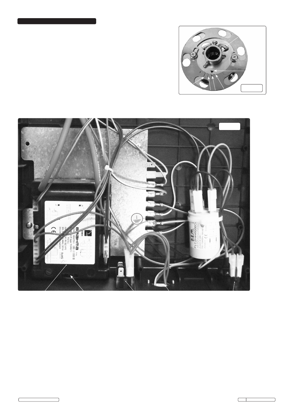
fig.13
4-Throttling damper disc phasing slots
[Setting 2]
7.1. Damper disc (or throttle adjustment)
The nozzle head sub assembly large disc is a close fit inside the blast
tube, hence directing and restricting (throttling) the air flow volume from
the fan through the slotted holes to the diffuser. The diffuser mixes the
supplied air with the fuel to give the optimum burn characteristics. This
optimum setting for each burner is preset in the factory and this position is
recorded and supplied with the heater instructions. The entire sub
assembly can be removed by loosening the cross head screw in the boss
shown in fig.12. If removed for cleaning for example, make a note of the
phasing notch (fig.13) in the damper ring that aligns with the triangle apex
in the bossed ring. It must be reassembled with the same notch to triangle
apex orientation.
Triangle
datum
Boss
1
2
4
3
Original Language Version
IR55 Issue: 3(I) - 19/02/15
© Jack Sealey Limited
7. FACTORY SETTING
Electrical hardware and wiring loom (see also fig.4)
Automatic control
digital system.
Fig.14
EMC Filter
Power on Lamp
"I"/"O"/"II"
Selector switch
Room thermostat
or timer socket.
(Room thermostat or
timer not supplied)
Reset button