Fig.5, Fig.6, Operation – Sealey IR55 User Manual
Page 4
6.1.
Starting the Heater.
NOTE: Always place on a flat, stable and level surface and check the electrical supply conforms to the data on the model plate. It is
preferable to start the heater outdoors for the first time to allow any oils left over from the manufacturing process to be burnt off safely; run
it for 10 minutes on this first burn. On first starting or if the heater is started after the oil tank has been emptied; the flow of oil to the burner
may be impaired by air in the circuit. In this case the automatic digital control system will cut out ("safety lockout system") the heater and it
might be necessary to renew the starting procedure by depressing the reset button on the control panel (fig.4). This button will illuminate;
wait two minutes before resetting. Repeat if necessary.
6.1.1. The drain plug is mid position beneath the tank and requires an 8mm hexagon key to operate. Ensure the plug is closed tight before care
fully filling the fuel tank with approved fuel through either filler neck.
DO NOT fill or drain whilst the heater is operating.
6.1.2. Ensure both fuel caps are secure after filling.
6.1.3.
Plug the power cord into a suitable power socket, indication of power will be shown by the power light illuminating in fig.4. If using an
extension lead see Section 1.1.11.
6.1.4. Set the selector switch to "I" (ON) and the heater will start. Select "O" to turn off; the heater flame will extinguish with the fan continuing
to run for approximately 90 seconds cooling the combustion chamber. Set the selector switch to "II" (ON) only when used in conjunction
with a timer or a room thermostat. If the heater ceases operating and goes into a misfire sequence; set the selector switch to the "O"
position and immediately switch the selector switch to the desired function "I" or "II".
Note:
The automatic digital control system of this heater is protected by a fuse in the module. If the heater fails to fire, check this fuse first,
and replace if necessary. Also check the power source fuse and ensure that the correct voltage is being provided to the heater.
6.2.
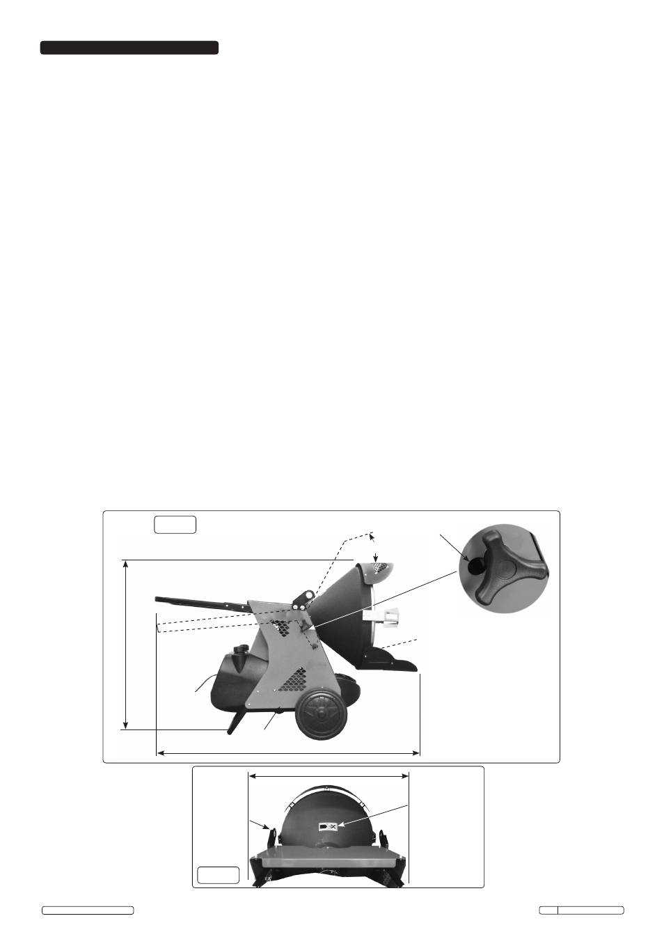
Inclined Feature.
6.2.1. The flow of heat can be directed horizontally or inclined upward with an approximate 10° angle from the horizontal. Loosen the hand screws
(fig.5) sufficiently but not completely from the side panels of the heater, using the handle bar as a lever locate the shoulder of the hand
screws in the required hole position, and tighten the hand screws to secure. Utilise the lower adjustable deflector as required, fully extended
when using horizontally to protect the floor for example.
6.3.
To Stop the Heater.
6.3.1. Select "O" position on the control panel. Combustion will stop, and the 'Cooling Cycle' (approximately 90 seconds) will begin.
6.3.2. When the 'Cooling Cycle' is completed the fan stops running and it is safe to unplug the heater.
WARNING! Unplugging the heater before the 'Cooling Cycle' has finished may cause overheating, possible damage to the heater
and heat plate, and will void the warranty.
6.4.
To Restart the Heater.
6.4.1. Be sure to follow all starting procedure precautions.
6.4.2. Wait ten seconds after cooling cycle has completed.
6.4.3. Start heater by pressing "I" position on the selector switch, if required and linked to timer or thermostat choose "II" position. Select "O" to
stop.
6.5.
Transporting.
6.5.1. Before the heater is moved it must be stopped and unplugged from the mains.
6.5.2. The heater must be totally cooled off.
6.5.3. Ensure tank breather and filler caps are securely closed.
6.5.4. For transporting short distances on level surfaces the handlebar and wheels are adequate. For more arduous locations and distances, lugs
are fitted for lifting with rope, slings or chains.
WARNING! During handling and transporting, oil may leak. The fuel and breather caps are not an absolute seal, enabling air to
enter and escape during operation. Never transport or service the heater while it is operating, while hot or plugged into the mains.
Severe burns or electric shock could occur.
Loosen the two hand screws
sufficiently but not completely
fig.5
Drain plug
10° Incline feature
Two holes joined
by smaller slot
Pivot
point
10°
Viewed from rear of burner
High temperature
warning label
Lifting lugs
fig.6
1410mm
1055mm
715mm Over wheels
Original Language Version
IR55 Issue: 3(I) - 19/02/15
© Jack Sealey Limited
6. OPERATION