Fig.8 fig.9, Fig.7 – Sealey IR55 User Manual
Page 5
Use only original equipment replacement parts. The use of alternate or third
party components can cause unsafe operating conditions, and will void the
warranty. We suggest following a maintenance schedule as follows.
6.1.
Fuel/Fuel Tank
Flush every 200 hours of operation or as needed.
DO NOT use
water to flush the tank. The drain plug position which is shown in
fig.3 and fig.5 requires an 8mm hexagon key to remove. It may be
necessary to elevate the heater as ground clearance is small. After
draining into a suitable container for recycling replace plug and
flush with a minimal amount of fresh kerosene/paraffin/diesel only.
Drain again into the container for recycling. Clean drain plug, seal
ring, seat and replace, tighten to seal.
6.2.
Filters
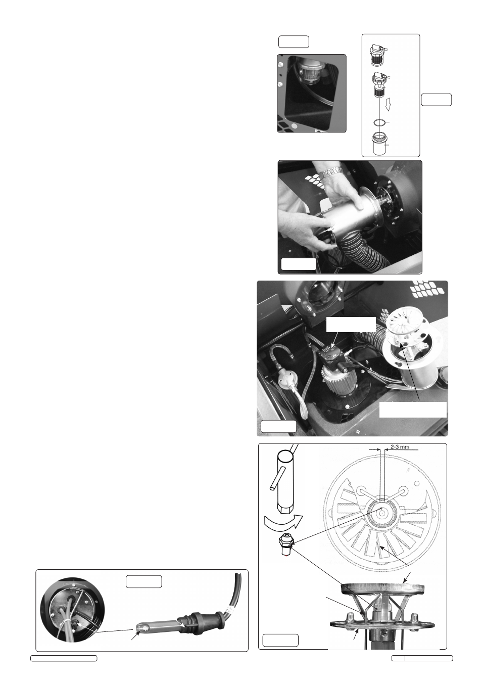
The Fuel Filter and Oil Filter should be cleaned every 50 hours by
rinsing them in clean kerosene/paraffin/diesel. The fuel filter can be
viewed, accessed and removed through a cutout in the side panel
(fig.7).This procedure shown in fig.8 should also be followed if the
fuel is found to be contaminated. Replace the filter if damaged or old.
6.3.
Nozzle
The nozzle should be cleaned or replaced at least once per heating
season. This procedure should also be followed if the fuel is
found to be contaminated.
6.3.1. Remove the top cover and apron above fuel tank to access the
blast tube area.
6.3.2. Remove the blast tube by unscrewing, not removing, the three
hexagon headed machine screws through the flange. Unscrew
approximately 4mm from the keyhole slots.
6.3.3. Rotate the blast tube anticlockwise until the large hole in the slots
aligns with the fixings and remove/slide holding the tube
horizontally (fig.9), finally resting the assembly as shown in fig.10.
Note! Some internal parts are delicate and care is required in this
process.
6.3.4 A 16mm A/F socket (fig.12) will be required to remove the nozzle. It
will be necessary, with care to spring electrodes apart in removal.
DO NOT remove the top diffuser or damper disc.
6.3.5. To clean dirt from the nozzle, blow compressed air through nozzle
nose. It may be necessary to soak the nozzle in clean kerosene/
paraffin/diesel to help loosen any particles (fig.12).
6.3.6. Replacement of the nozzle and blast tube is the opposite of removal.
6.4.
Electrodes
Clean and re-gap every 600 hours of operation (fig.12), ensure
electrode gap is between 2-3mm and they do not touch other
components . To clean or replace the electrodes, the blast tube will
require partial removal as described in 6.3.2, 6.3.3 and 6.3.4.
6.4.1. Offer a long screwdriver through the damper disc hole and slot to
remove the cross head screw from the electrode tab.
6.4.2. "Unplug" locally the electrode from the high tension (HT) lead.
6.4.3. After removing the electrode, clean with a wire brush or replace.
6.5. Photocell
The Photocell should be cleaned at least once per heating season
or more depending on conditions. It will be necessary to access the
blast tube by removing the apron above the fuel tank as in 6.3.1.
6.5.1. Remove by pulling straight against the small resistance offered.
6.5.2. Use a cotton swab dipped in water or alcohol to clean the lens of the
Photocell (fig.11).
6.5.3. Align tang with a slot in the insert bush and replace by pushing
straight against the small resistance offered.
6.6.
Long Term Storage.
6.6.1. Unscrew the drain plug and drain fuel into a suitable container (fig.3
and fig.5) Using a small amount of kerosene/paraffin/diesel, rinse
and swirl the fuel around the fuel tank. Empty the tank completely.
(All as described in 6.1)
6.6.2.
Never store leftover kerosene/paraffin/diesel over the summer.
Using old fuel can damage the heater.
6.6.3. Store heater in a dry, well ventilated area.
6.6.4. Be sure that the storage area is free of dust and corrosive vapours.
Keep this User’s Manual in an easily accessible place.
Factory set (P)
DO NOT adjust
Factory set damper
disc
DO NOT adjust
fig.8
fig.9
Location tang
fig.7
Loosen
fig.10
fig.12
fig.11
Rotate sight
glass to remove
Filter
"O" Ring
gasket
Sight glass
Strainer
Lens
Blast tube rear
Electrodes
Electrode gap
Damper throttle disc
Diffuser
Original Language Version
IR55 Issue: 3(I) - 19/02/15
© Jack Sealey Limited