Sealey LED045S User Manual
Page 2
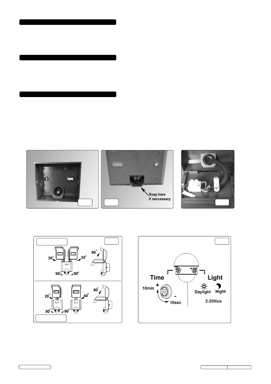
4.9
The lamp unit may be pointed down to a maximum of 90º and panned to 30º for the LED046S and 20º left, 40º right for the LED045S
(fig.4).
4.10. The detector head may be moved to 90º in each direction.(fig.4)
4.11. The infra-red detector is equipped with two adjusting dials (fig.5).
4.11.1. The left hand dial determines the interval that the light will remain illuminated having been triggered.
4.11.2. The right hand dial controls the light level at which the lamp is triggered. The unit should switch on at dusk at approx. 30lux.
4.11.3. When installed at 3m above ground level, the detection range is approximately 10m.
2. INTRODUCTION
Motion detector unit switches on when approached by vehicles or persons. Mounted in die-cast aluminium housings with pre-drilled holes for
wall mounting. Features 4 (LED045S) or 8 (LED046S) high power Epistar™ LEDs mounted in a swivelling head. Supplied without mains cable
and suitable for outdoor mounting.
3. SPECIFICATION
Model No: . . . . . . . . . . . . . . . . . . . . . . . . . . . . . . . . . . LED045S . . . . . . . . . . . . . . . . . . . . . . . . . . . . . . . . . LED046S
Power: . . . . . . . . . . . . . . . . . . . . . . . . . . . . . . . . . . . . . 10W . . . . . . . . . . . . . . . . . . . . . . . . . . . . . . . . . . . . . . . . . 20W
Lumen Output: . . . . . . . . . . . . . . . . . . . . . . . . . . . . . . . 720lm . . . . . . . . . . . . . . . . . . . . . . . . . . . . . . . . . . . . . .1440lm
Supply: . . . . . . . . . . . . . . . . . . . . . . . . . . . . . . . . . . . . . 230V . . . . . . . . . . . . . . . . . . . . . . . . . . . . . . . . . . . . . . . . 230V
4. INSTALLATION
DO NOT connect to the electrical supply until the installation is complete.
4.1.
The maximum mounting height for mounting the light is 3m from the ground.
4.2.
Remove the mounting plate from the control box by removing the screw on either side. Mark the area on which the lamp is to be
mounted, using the plate as a template (fig.1).
4.3.
Ensure that the two marks are level and drill ready to receive the screws, using masonry plugs if necessary.
4.4.
If the cable is to be led from the bottom of the mounting plate, carefully snap the plastic web from the cut-out behind the grommet (fig.2).
4.5.
Feed the end of the supply cable (1mm² cross sectional area) through the grommet and
screw the mounting plate to the wall.
4.6.
Connect the live (brown) and neutral (blue) wires to the live and neutral terminals in the connector block (fig.3). This lamp is double
insulated, and does not require earthing.
4.7.
Replace the control box on the mounting plate and secure by inserting and tightening the screw on either side.
4.8.
It is now safe to connect to the mains supply.
fig.1
fig.4
fig.2
fig.3
fig.5
LED046S
LED045S
Original Language Version
© Jack Sealey Limited
LED045S,LED046S Issue:1 14/04/14