Shelf 3000 series switch backplane cables -6, Shelf 3000 series switch setup -6 – EFJohnson 3000 SERIES User Manual
Page 32
SYSTEM RACK
4-6
6. On the top Backplane board, the following measure-
ments should be referenced to ground (pins 9, 10, 41
or 42).
Center Pin of
Ohms
J5
37.5
J6
37.5
J23
19.2
J24
19.2
NOTE: The four readings should be ±1 ohm from
the test specifications.
7. Test is completed.
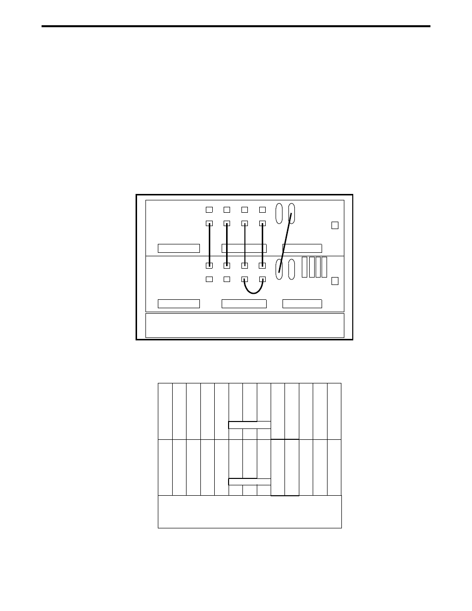
Figure 4-1 2-SHELF 3000 SERIES SWITCH BACKPLANE CABLES
Figure 4-2 2-SHELF 3000 SERIES SWITCH SETUP
NIM SHELF
P33
SHELF 1
P33
SHELF 2
J1
J2
J26
J25
J4
J3
J24
J23
J6
J5
J103
J102
J101
J1
0
0
J1
J2
J26
J25
J4
J3
J24
J23
J6
J5
POWER SUPPLY
J22
J21
J20
J22
J21
J20
P
T
M
P
T
M
0
1
2
3
4
5
6
7
8
9
10
11
16
17
18
19
20
21
22
23
24
25
26
27
SHELF 1
SHELF 2
M
D
C
M
D
C
M
C
I
M
C
I
M
C
I
M
C
I
t
N
e
M
V
T
M
V
T
1
2
M
S
N
M
S
N
M
I
T
M
I
T
M
I
T
M
I
T
M
C
C
M
C
C
POWER SUPPLY
N
I
M
t
N
e
N
I
M
M
L
E
M
L
E
M
W
A
M
W
A
M
I
D
M
I
D