Section 23 backplane, 1 description, 2 backplane setup procedure – EFJohnson 3000 SERIES User Manual
Page 181: 1 shelf address settings, 2 termination settings, 3 jumper definitions and settings, Backplane, Description, Backplane setup procedure, Shelf address settings -1
23-1
BACKPLANE
SECTION 23 BACKPLANE
23.1 DESCRIPTION
The 3000 Series Switch shelf backplane contains
slots that modules are inserted into, to derive the
module address. The backplane distributes:
•
Power
•
PCM paths
•
Master clock
•
Master sync
•
Intra-Terminal data bus
•
Channel status bus
•
Control lines for data busses
The backplane has active circuitry that distributes
PCM paths, master clock and master sync. The back-
planes are connected together for complete distribu-
tion of receive and transmit signals to all shelves
within the Switch.
23.2 BACKPLANE SETUP PROCEDURE
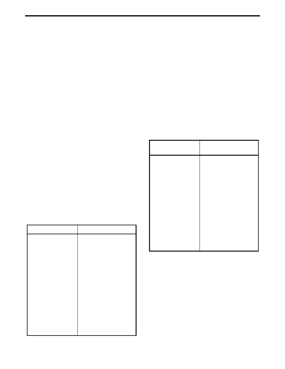
23.2.1 SHELF ADDRESS SETTINGS
Using the following table, determine the settings
of Switch 1 for the Shelf Address of each shelf.
23.2.2 TERMINATION SETTINGS
Using the following table, determine the switch
settings for switches 2 through 8. All switches are
37.5 ohms and normally set for 6 shelves.
•
S2 - VTM PCM
•
S3 - Primary Tx PCM
•
S4 - Primary Rx PCM
•
S5 - Master Sync
•
S6 - Master Clock
•
S7 - Secondary Rx PCM
•
S8 - Secondary Tx PCM
23.2.3 JUMPER DEFINITIONS AND SETTINGS
1. External Cable Connections
•
J1/J2 - Shelf Interconnect
2. Primary Audio Connections
•
J3/J5 - Primary Rx PCM
•
J2/J4 - Primary Tx PCM
3. Secondary Audio Connections
•
J23/J25 - Secondary Rx PCM
•
J24/J26 - Secondary Tx PCM
Table 23-1 SHELF ADDRESS SETTINGS
Shelf Number
Switch 1, Open Sections
1
2
3
4
5
6
7
8
9
10
11
12
13
14
15
16
17
18
ALL Closed
1
2
1,2
3
1,3
2,3
1,2,3
4
1,4
2,4
1,2,4
3,4
1,3,4
2,3,4
1,2,3,4
5
1,5
Table 23-2 TERMINATION SETTINGS
Number of Shelves
Switch Sections
CLOSED
2
3
4
5
6
7
8
9
10
11
12
13
14
15
16
17
18
ALL
1,3,6,7,8
1
2,4,5,6,7,8
2,5,6,7,8
2,7
3,4,5,6,8
3,4,6,7
3,4,8
3,5,6
3,5
3,6,8
3,7
3
4,5,6,7,8
4,5,6,7
4,5,6