3 8-position dip switch s201, Position dip switch s201 -5, E&m interface connections -5 – EFJohnson 3000 SERIES User Manual
Page 115: S201 -5, E&m card s201 dip switch settings -5, Telephone interface module (tim) 14-5, On off on on on off off on, Off on off on off off off on, Off on on on on off off on, Off on off off on off on
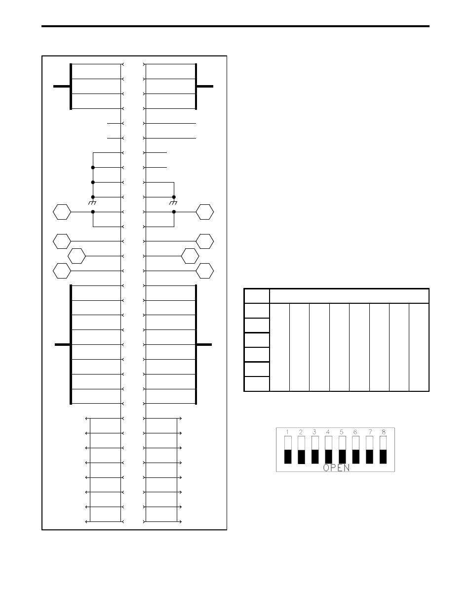
TELEPHONE INTERFACE MODULE (TIM)
14-5
Figure 14-2 E&M INTERFACE CONNECTIONS
14.2.3 8-POSITION DIP SWITCH S201
The 8-position DIP switch S201 determines the
interface type. There are five types of E&M interface
signaling, Type I through Type V.
C A U T I O N
Do not adjust S201 with the E&M card connected in
any way to the Switch. Damage to the E&M card
could result.
Refer to Table 14-1 for S201 configurations for
each type of signaling.
NOTE: S201 positions 7 and 8 are for E-Lead detec-
tion type.
Figure 14-3 S201
NOTE: Black is switch position
.
22
23
24
25
26
27
28
29
30
31
32
20
19
16
15
64
63
62
61
60
59
57
56
55
54
53
52
51
48
47
21
43
44
45
46
11
12
13
14
1
33
34
35
36
37
38
39
40
41
42
2
3
4
5
6
7
8
9
10
58
49
50
17
18
S1, P4
S1, P3
S1, P2
S1, P1
+5V
+12V
-12V
-48V
MAS SYNC
MAS CLK
TX PCM
RX PCM
CSB DATA
IDB DATA
IDB IDLE
VTM PCM
CSB IDLE
ALM +
ALM -
1
2
3
4
5
6
7
8
TXS+
TXS-
MA
MB
TXA+
TXA-
8
7
6
5
4
3
2
1
RXS+
RXS-
EA
EB
RXA+
RXA-
CSB IDLE
VTM PCM
IDB IDLE
IDB DATA
CSB DATA
RX PCM
TX PCM
MAS CLK
MAS SYNC
-48V
-12V
+12V
+5V
SEC TX PCM
SEC RX PCM
S1, P8
S1, P7
S1, P6
S1, P5
SB
SG
M-LEAD
E-LEAD
TX+
TX-
RX+
RX-
Table 14-1 E&M CARD S201 DIP SWITCH
SETTINGS
Type
Position
1
2
3
4
5
6
7
8
I
On
Off
On
On
On
Off
Off
On
II
Off
On
Off
On
Off
Off
Off
On
III
Off
On
On
On
On
Off
Off
On
IV
Off
On
Off
On
Off
Off
Off
On
V
Off
Off
On
Off
Off
On
Off
On