Host interface module, Master development software, About antennas – Linx Technologies MDEV-xxx-ES User Manual
Page 8
–
–
–
–
10
11
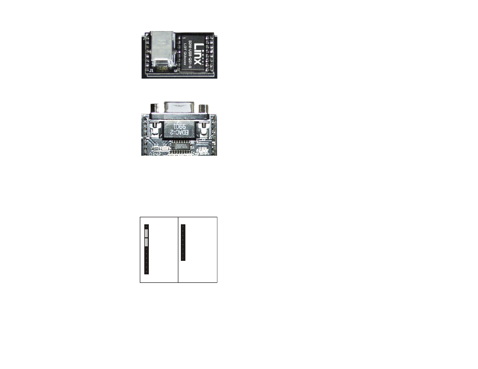
Host Interface Module
The ES Master Development System
features a Host Interface socket, which
allows the use of two different PC interface
modules. The first is a USB interface
module that uses a standard USB cable to
connect to a PC’s USB port or a USB hub.
The second type of module is a RS-232
interface module that can be connected
to a standard serial COM port on a PC
using a straight-through 9-pin extension
cable (not included). The evaluation board
is considered a DCE device and as such
is designed to be connected using a
straight-thru serial extension cable. Do not
use a null-modem cable as the boards will
not function.
To install, select the module to be used
and then line up the pins on the module
with the headers on the board. Verify that the pin one polarity marks on the
board and on the Host Interface Module match. The USB jack or the D-sub
connector should face away from the board. Press firmly on the module so
that it slides fully into the header.
The development system may be prepared
for host operation with the supplied Linx
software by setting the jumpers on the
header as shown in the adjacent figure.
This routes the module’s data lines to
the Host Interface Module. Despite being
electrically interfaced, appropriate protocol
must be employed to ensure reliable and
error-free data transfer since the ES Series
modules do not encode or packetize the
data in any manner. It is important to understand that the development
boards are transparent; that is, the user’s software is entirely responsible
for controlling the timing and error correction aspects of the link. The
evaluation boards have no provision to check or qualify the incoming data.
When designing a protocol to transfer data across a wireless link, it is very
important to remember that interference is inevitable. The protocol must
Figure 7: USB Interface Module
Figure 8: RS-232 Interface Module
TS1
TX
RX
TS2
SQ. DATA
NC
AUDIO REF
AUDIO
RSSI
RX DATA
RX DECODER
RX PDN
PDN ENC
TX PDN
PDN RS232
TX RS232
TX DATA
TX ENCODER
/CLK
/CLK SEL
LO V DET
NC
GND
TS1
TX
RX
TS2
SQ. DATA
NC
AUDIO REF
AUDIO
RSSI
RX DATA
RX DECODER
RX PDN
PDN ENC
TX PDN
PDN RS232
TX RS232
TX DATA
TX ENCODER
/CLK
/CLK SEL
LO V DET
NC
GND
Figure 9: Jumper Configuration
support error detection and correction if it is to be successful. A correctly
designed protocol will provide optimum performance and throughput for
product specific applications while taking into account the timing and
data-rate requirements of the module. For further information on protocol
considerations please refer to Application Note AN-00160.
If the designer needs to develop protocols using a physical implementation
other than an RS-232 or USB interface, the designer can build the custom
interface circuitry in the prototyping area and route the module’s data
signals from the header to the prototyping area.
Master Development Software
The development system is supplied with Windows-based software that
facilitates communication with the development boards through the Host
Interface Module. This software allows for testing and illustrates basic
implementation of the modules as a wireless serial link. The user selects
either a USB or RS-232 connection and whether the connected board is
the transmitter or receiver. The user can then send text, ASCII characters,
and even a picture. Documentation for the software may be found by going
to the ‘Help’ menu then ‘Help File’.
Terminal emulation programs, such as HyperTerminal, do not provide
error correction; therefore, bit errors or data line hashing are displayed as
random characters. Some form of error detection should be employed
when developing a protocol for wireless environments (please see
Application Note AN-00160).
About Antennas
The choice of antennas is one of the most critical and often overlooked
design considerations. The range, performance, and legality of an RF link
are critically dependent upon the type of antenna employed. Linx offers
a variety of antenna styles that can be considered for a design. Included
with the kit is a Linx CW Series connectorized whip antenna that should
be connected prior to using the kit. Despite the fact that the antenna is
not centered on the board’s ground plane, it exhibits a VSWR of <1.7 and
suitably demonstrates the module’s best practical performance.