Front components, Chapter 2, System components – Lanner LEC-2220 User Manual
Page 9
9
System Components
Chapter 2
Embedded and Industrial Computing
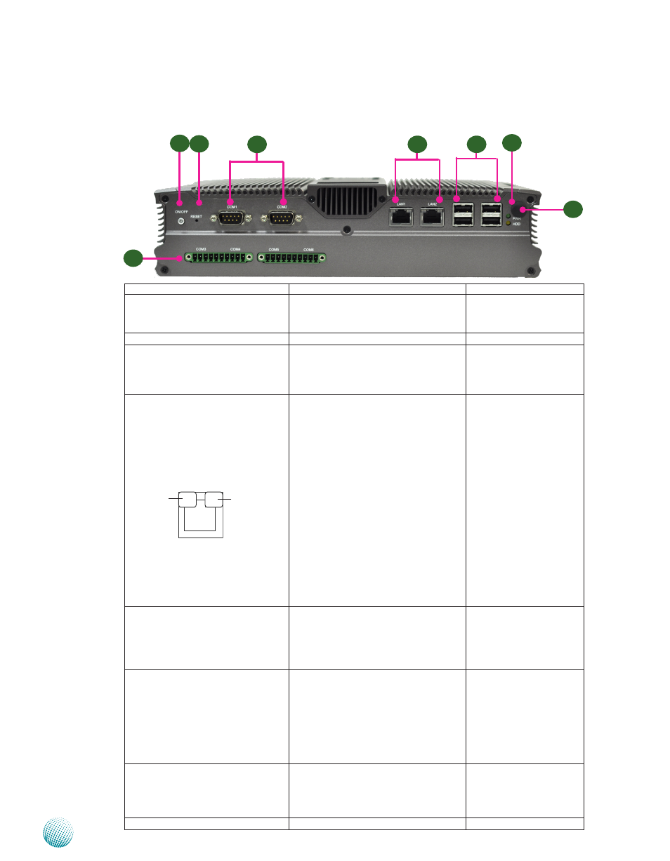
Front Components
Component
Description
Pin Definition Reference
F1 Power Button with dual LED
ATX Power-on button with LEDs:
Standby mode in Red; Power-on mode
in Green
F2 Reset
Reset switch
SW9 on page 17
F3 Serial Ports
Serial ports through the DB-9 connector;
COM1 supports RS-232 and COM2
supports RS-232/422/485 with switch
selection among RS-232/422/485.
CN15, CN16 on page 14
F4 Two 10/100/1000Mbps LAN ports Two RJ-45 (network) jacks with LED
indicators as described below. The LAN
ports are provided by Intel 82574L.
They both support WOL/Remote-
wake-up/PXE function.
LINK/ACT (Yellow)
On/Flashing: The port is linking
•
and active in data transmission.
Off: The port is not linking.
•
SPEED (Green/Amber)
Amber: The connection speed is
•
1000Mbps.
Green: The connection speed is
•
100Mbps
Off: .The connection speed is
•
10Mbps.
LAN Ports (CN13/CN14)
on page 15
F5 Four USB 2.0 Ports
An USB type A connector. In addi-
•
tion to this connector, an internal
pin header is easily access from the
back compartment where the PCI/
PCIe expansion slot locates.
Dual USB Port Connectors
(USB1, USB2) on Page 16
F6 HDD (Yellow) and
Power LED (Green)
HDD
Blinking: data access activities
•
Off: no data access activities
•
Power
On: The computer is on.
•
Off: The computer is off .
•
F7 Four Serial Ports
COM3 provide RS232/RS422/RS485
communications with a dip switch
selecting among these standards.
COM4~COM6 provide RS232
communication only.
RS-232 COM Port (J9 on
page 15)
F8 Antenna Hole
Reserved for antenna
sPEEd
LINK/ACT
F1
F2
F3
F4
F5
F7
F6
F8