Chapter 3, Board layout – Lanner LEC-2220 User Manual
Page 16
16
Board Layout
Chapter 3
Embedded and Industrial Computing
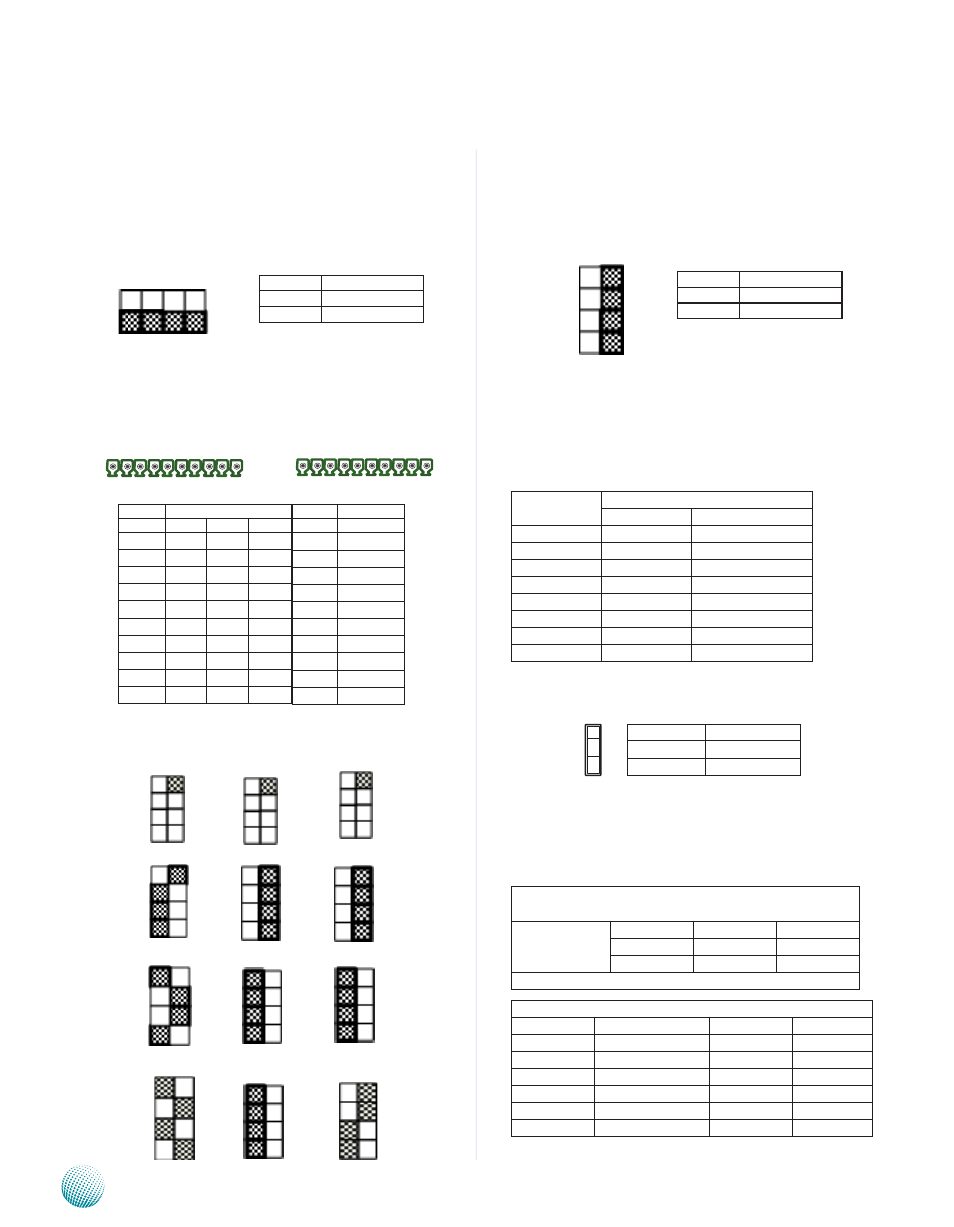
SW5: Select COM2 Termination in RS-485 (SW5) This
switch is used to enable or disable the signal termination
for COM2. We strongly recommend that you disable
termination when the port is configured as RS-232 and
enable it when the port is configured as RS-485/RS-422.
RS-232/422/485 Serial Port(COM3~COM6, J9 on
the backside): It is a RS-232 port through the D-SUB9
connector. Note that only COM3 can select among
RS232/422/485.
SW1, SW6, and SW7: Select COM3 Protocol Setting
RS-232
RS-422
RS-485
SW8: Select COM3 Termination in RS-485 (SW8): This
switch is used to enable or disable the signal termination
for COM3. We strongly recommend that you disable
termination when the port is configured as RS-232 and
enable it when the port is configured as RS-485/RS-422.
LAN1/LAN2 Ports (CN13/CN14): The LAN ports are
provided by Intel 82574L Ethernet controller whose
interface complies with PCI-e 1.1 (2.5 Ghz). It has advanced
management features including IPMI pass-through via
SMBus or NC-SI, WOL, PXE remote boot, ISCSI boot and
VLAN filtering.
Pin No.
Description
Fast Ethernet Gigabit Ethernet
1
TX+
BI_DA+
2
TX-
BI_DA-
3
RX+
BI_DB+
4
--
BI_DC+
5
--
BI_DC-
6
RX-
BI_DB-
7
--
BI_DD+
8
--
BI_DD-
Clear CMOS jumper (JP1): It is for clearing the CMOS
memory.
Digital I/O (CN6)
Digital IN/OUT(DIO1) Connector: The 8 pins of General
Purpose Input/Output (GPIO) support input and output
operations through the DB-9 female connector.
TTL Level is +5V; Maximum input/output current for
each port is 64mA
Input/Output Voltage
Logic
Register
0~2V
Low
0
2~5V
High
1
The default value is 0
DIO Address
Address
Description
Address
Description
0x2e
SUPERIO_INDEX 0x08
GPIO3
0x2f
SUPERIO_DATA
0x10
GPIO4
0x07
BANK_REG
0x20
GPIO5
0x01
GPIO0
0x40
GPIO6
0x02
GPIO1
0x80
GPIO7
0x04
GPIO2
Pin No.
Pin Name
1-2
Normal (default)
2-3
Clear CMOs
1
2
3
1 2 3 4 5 6 7 8 9 10
COM5 COM6
11 12 13 14 15 16 17 18 19 20
COM3 COM4
Pin No.
Pin Name
Rs-232 Rs-422 Rs-485
1
RTs3#
TX+ dATA+
2
sIN3
TX-
dATA-
3
sOUT3 RX+
NC
4
CTs3#
RX-
NC
5
GNd
GNd
GNd
6
RTs4#
7
sIN4
8
sOUT4
9
CTs4#
10
GNd
Pin No. Pin Name
Rs-232
11
RTs5#
12
sIN5
13
sOUT5
14
CTs5#
15
GNd
16
RTs6#
17
sIN6
18
sOUT6
19
CTs6#
20
GNd
Pin No.
Function
sW8 on
Enable termination
sW8 off
disable termination
Off On
SW8
SW1
1
2
3
4
Off On
SW6
1
2
3
4
Off On
SW7
4
3
2
1
On Off
SW5
OFF
ON
Pin No.
Function
sW5 on
Enable termination
sW5 off
disable termination