Chapter 3, Board layout – Lanner LEC-2220 User Manual
Page 17
17
Board Layout
Chapter 3
Embedded and Industrial Computing
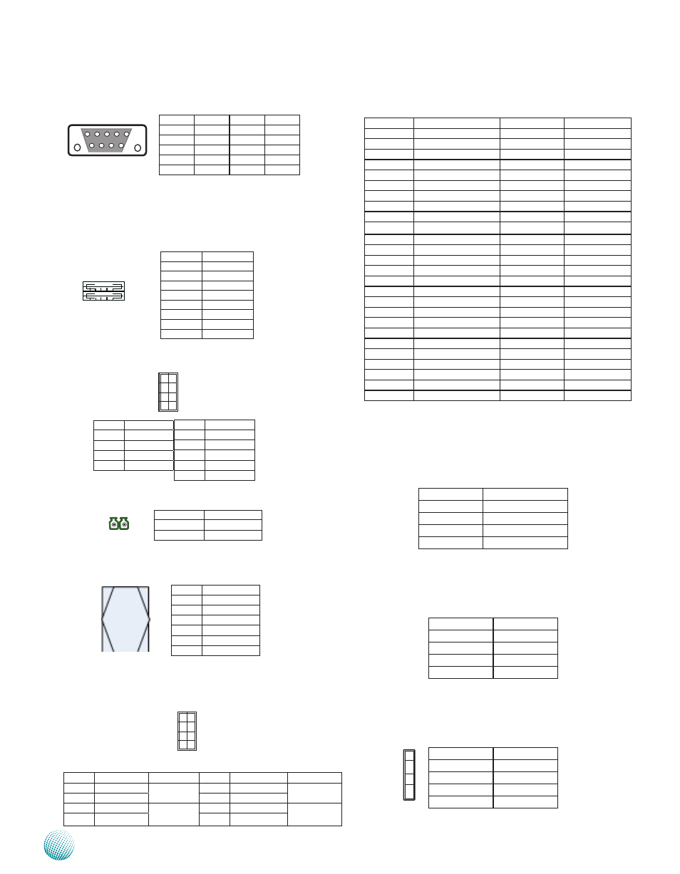
Mini PCI Express Connector (CN9):
PIN
Pin Name
PIN
Pin Name
1
WAKE#
27
GNd
2
+3.3V
28
+1.5V
3
Reserved
29
GNd
4
GNd
30
sMB_CLK
5
Reserved
31
PETn0
6
1.5V
32
sMB_dATA
7
CLKREQ#
33
PETp0
8
REsERVEd
34
GNd
9
GNd
35
GNd
10
REsERVEd
36
UsB_d-
11
REFCLK-
37
RsVERd
12
REsERVEd
38
UsB_d+
13
REFCLK+
39
RsVERd
14
REsERVEd
40
GNd
15
GNd
41
REsERVEd
16
REsERVEd
42
REsERVEd
17
REsERVEd (UIM_C8)
43
REsERVEd
18
GNd
44
REsERVEd
19
REsERVEd (UIM_C4)
45
REsERVEd
20
ENABLE
46
REsERVEd
21
GNd
47
REsERVEd
22
PERsT#
48
+1.5V
23
PERn0
49
REsERVEd
24
+3.3Vaux
50
GNd
25
PERp0
51
REsERVEd
26
GNd
52
+3.3V
Audio Output (CN3)
Pin No.
Description
1,3
GND
2
AUDIO_OUT_L
4
AUDIO_JD
5
AUDIO_OUT_R
Microphone Input (CN4)
Pin No.
Description
1,3
GND
2
MIC_OUT_L
4
MIC_JD
5
MIC_OUT_R
Line-in (J2)
Pin No.
Description
1
LINE_OUT-R
2
LINE_JD
3
LINE_OUT-L
4
GND
Dual USB Port Connector #0 and #1 (USB1):
Dual USB Port Connector #2 and #3 (USB2)
USB 2.0 Pin Header (J11, USB#4 and #5):
External Power Button (J1):
SIM Card Socket (CN8):
Front Panel Function Pin Header (J5, on the backside):
It provides LED signal and button function on the front
panel.
Pin No.
Pin Name
Function
Pin No.
Pin Name
Function
1
Hd_LEd+
Hdd LEd
2
PWR_LEd+
Power LEd
3
Hd_LEd-
4
PWR_LEd-
5
Reset
system Reset
Button
6
POWER_BTN- Power On/Off
Push Button
7
GNd
8
GNd
Pin No.
description
C1
UIM_PWR
C2
UsIM_REsET
C3
UsIM_CLK
C5
GNd
C6
UsIM_VPP
C7
UsIM_dATA
PIN NO.
dEsCRIPTION
1
PWR_BTN_N
2
GNd
1
3
5
7
2
4
6
8
1 2
C5 C7
C1 C3
1 2 3 4
5 6 7 8
Pin No.
Pin Name
1
+5V
2
UsBd0-
3
UsBd0+
4
GNd
5
+5V
6
UsBd1-
7
UsBd1+
8
GNd
Pin No. Pin Name
1
+5V
3
UsBd4-
5
UsBd4+
7
Ground
Pin No. Pin Name
2
+5V
4
UsBd5-
6
UsBd5+
8
Ground
10
NC
10
8
6
4
2
9
7
5
3
1
Pin No.
Pin Name
1
Input0
2
Input1
3
Input2
4
Input3
5
GNd
Pin No.
Pin Name
6
Output0
7
Output1
8
Output2
9
Output3
9 8 7 6
5 4 3 2 1
1
2
3
4