Chapter 2, System components, Rear components – Lanner LEC-2136 User Manual
Page 9
9
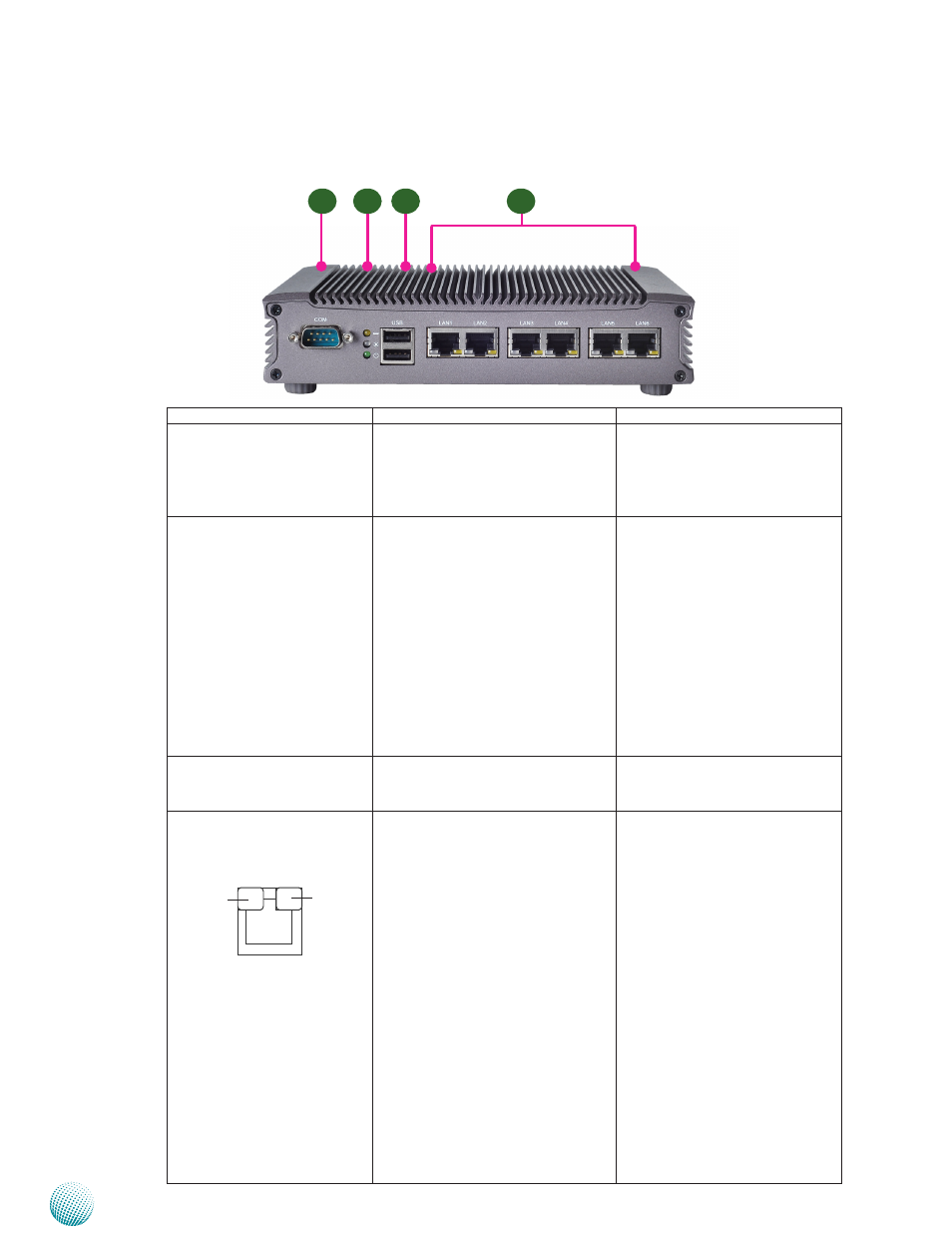
System Components
Chapter 2
Embedded and Industrial Computing
Rear Components
Component
Description
Pin Definition Reference
R1 Serial Port COM1
Serial ports through the DB-9
connector; COM1 supports RS-
232 protocol. The system also has
another COM port (COM2) via the
internal pin header.
COM1on page 13
R2 HDD (Yellow), Status and
Power LED (Green)
HDD
Blinking: data access activities
•
Off: no data access activities
•
Status. This LED can be programmed
to behave like this (refer to the Driver
and User Manual CD for sample code):
Red: abnormal condition arises
•
Off: normal operation
•
Power
On: The computer is on.
•
Off: The computer is off .
•
R3 Dual USB2.0 Stack
Connector
An USB type A connector.Besides
this one, there is another Dual USB
connectors on the front panel.
CN7 on Page 14
R4 Dual 10/100/1000 LAN
Ports
Two RJ-45 (network) jacks with LED
indicators as described below. The
LAN ports are provided by Intel
82574L and 82583V. The LAN1
(powered by 82574L) can serve
management functions including
the PXE (Preboot eXecution
Environment; you need to turn on the
PXE in the BIOS).
LINK/ACT (Yellow)
On/Flashing: The port is linking
•
and active in data transmission.
Off: The port is not linking.
•
SPEED (Green/Amber)
Amber: The connection speed is
•
1000Mbps.
Green: The connection speed is
•
100Mbps
Off: .The connection speed is
•
10Mbps.
LAN1/LAN2/LAN3 on page 14
R1
R2
R3
R4
SPEED
LINK/ACT