Chapter 3, Board layout, Connectors and jumpers list – Lanner LEC-2136 User Manual
Page 12
12
Board Layout
Chapter 3
Embedded and Industrial Computing
Connectors and Jumpers List
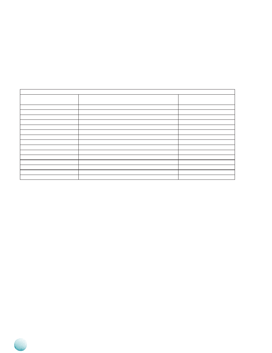
The tables below list the function of each of the board
jumpers and connectors by labels shown in the above
section. The next section in this chapter gives pin
definitions and instructions on setting jumpers.
Table 3.1 Connector List for LEB-2136
Labels
Function
Pin Definition Reference
Page
CN2
Power Button Connector
P14
CN4
CompactFlash Connector
P14
CN6
Mini-PCIe Connector
P14
CN7
USB 1&2 Connector
P14
CN9
DC_IN Power Connector
P14
CN10
USB 3&4 Connector
P14
COM1
RS-232 Communication Port
P13
J6
Serial-ATA Data Port
P13
J8
Serial-ATA Power Connector
P13
J9
RS-232 Communication Pin Header
P13
JP1
CMOS reset
P13
JP2
Hardware or Software Reset Selection Jumper
P13
LAN1/LAN2/LAN3
Ethernet Ports
P14
SW1
Reset Button
P13
VGA1
VGA Connector
P13
- LVC-2000 (39 pages)
- LVC-5000(N4) (42 pages)
- LVC-5550S (41 pages)
- LVC-5570 (48 pages)
- LVC-5770 (49 pages)
- FW-6432 (16 pages)
- FW-7525 (41 pages)
- FW-5330 (38 pages)
- FW-6486 (18 pages)
- FW-6436 (19 pages)
- FW-7573 (44 pages)
- FW-7568 (52 pages)
- FW-7540 (47 pages)
- FW-8759 (47 pages)
- FW-7581 (23 pages)
- FW-8758 (42 pages)
- FW-7610 (44 pages)
- FW-8756 (24 pages)
- FW-7575 (48 pages)
- FW-8760 (53 pages)
- FW-8877 (46 pages)
- FW-8892 (58 pages)
- FW-8893C (49 pages)
- FX-3411 (48 pages)
- FW-8894 (31 pages)
- FW-8771 (47 pages)
- RS12-38800 (64 pages)
- MR-320 (20 pages)
- FX-3210 (54 pages)
- MR-301 (16 pages)
- MR-350 (12 pages)
- MR-330A (16 pages)
- MR-730 (18 pages)
- VES-220 (19 pages)
- VES-270 (19 pages)
- VES-310 (15 pages)
- VES-310 V2 (20 pages)
- VES-500 (21 pages)
- EM-F345 (30 pages)
- VES-8X2 (16 pages)
- VES-8X6 (17 pages)
- LEC-2026 (67 pages)
- LEC-2010 (65 pages)
- LEC-2050 (38 pages)