Chapter 2, System components, Front components – Lanner LEC-2136 User Manual
Page 8
8
System Components
Chapter 2
Embedded and Industrial Computing
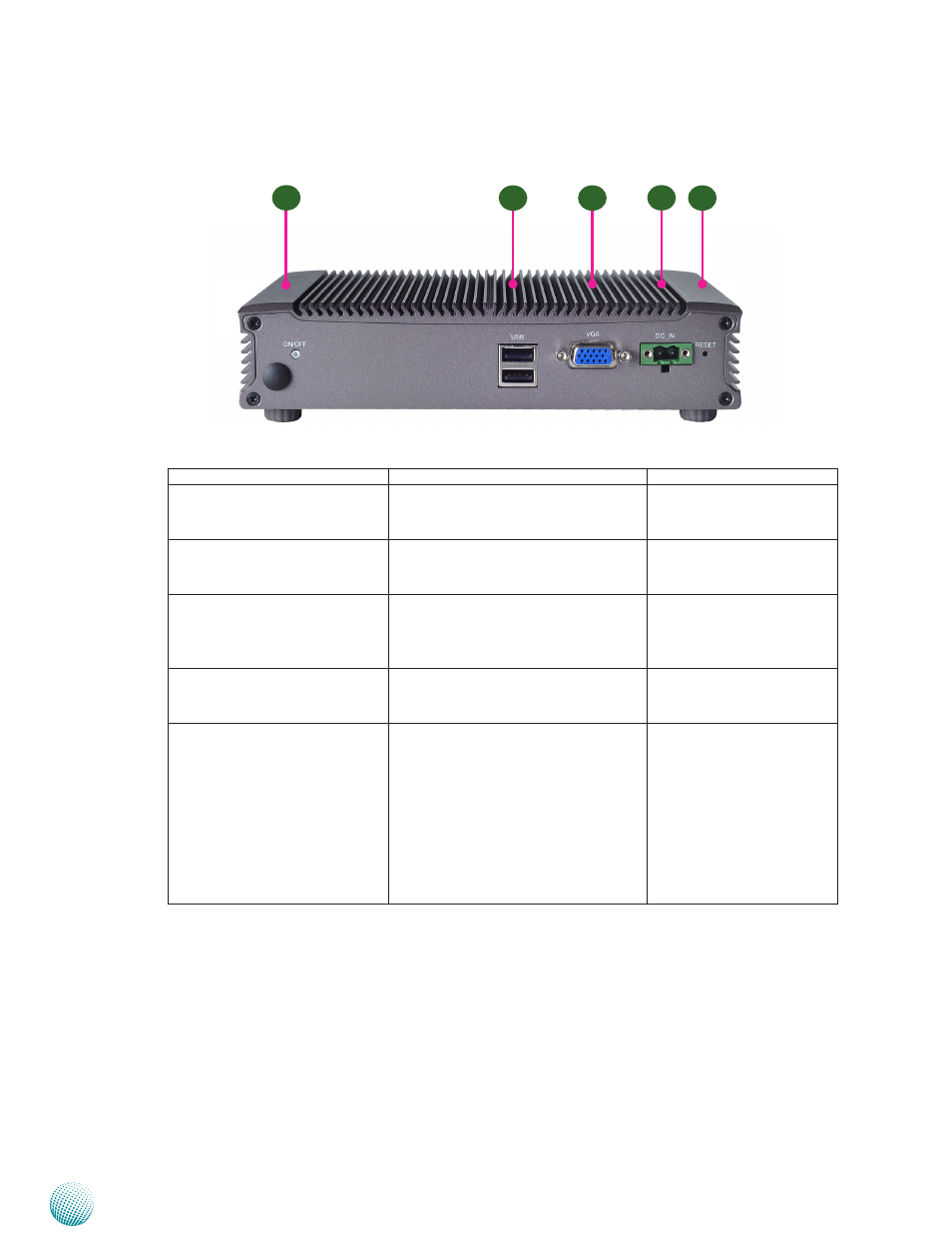
Front Components
Component
Description
Pin Definition Reference
F1 Power Button with dual LED ATX Power-on button with LEDs:
Standby mode in Red; Power-on mode
in Green
CN2 on page 14
F2 Dual USB 2.0 Stack Connector An USB type A connector. Besides this
one, there is another Dual USB connec-
tors on the back panel.
CN10 on page14
F3 VGA Port
The VGA port is provided by integrat-
ed Graphics Media Accelerator 3150.
The displays can support VGA up to
2048x1536.
VGA1 on page 13
F4 DC-In (power)
Power-in Connector through 1x2 Pin
Phoenix Contact Connector. The input
power should be 24V 2.5A.
CN9 on page 14
F5 Reset
Reset switch
The reset switch can be programmed
to be either a software or hardware
reset. The software reset can set the
designated software to its default
settings. The hardware reset will
trigger the reset signal and reboot the
whole system. Refer to JP2 jumper
in Chapter 3 Board Layout and the
sample code on the Driver and User
Manual CD.
SW1 on page 13
F1
F2
F3
F4
F5