Chapter 2, System components, Front features – Lanner VES-500 User Manual
Page 8
8
System Components
Chapter 2
Embedded and Industrial Computing
F3
F1
F2
F4
F5
F6
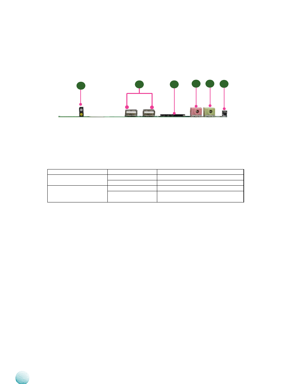
Front Features
F1 Power (Green) /HDD (Yellow) LEDs
LED
Behavior
Interpretation
Power (Green)
On/Flashing
The system is powered on.
Off
The system is powered off..
HDD (Yellow)
Flashing
It indicates data access activity
Off
There are no data access activities or no
hard disk present
F2 Two USB 2.0 Ports (left: USB Host, right: USB On-The-Go)
The left one is Host USB; the left one can act as a host as well as a device with jumper settings. Refer to
pin HOSTUSB1 and OTGUSB1 in Chapter 3 Motherboard Information for pin definitions.
F3 SD Card Connector
Refer to pin SDC1 for pin definitions in Chapter 3 Motherboard Information.
F4 F5 Microphone/Line-out Connector
Refer to pin MIC1 and Front1 for pin definitions in Chapter 3 Motherboard Information.
F6 Reset Button
It is a reset button to turn on or off the power. The reset button can act as a hardware to reset the entire
system or software reset to reset the designated software to its default. It can also be used as power
on/off switch with jumper settings. Refer to Pin RST1 and SW3 for more information on jumper settings
in Chapter 3 Motherboard Information .