Appendix a, Appendix a: programming the mcu, Digital input/output control – Lanner VES-500 User Manual
Page 18
18
Digital Input/Output Control
Appendix A
Embedded and Industrial Computing
Appendix A:
Programming the MCU
The MCU programs is by way of the follwing method:
Host communication interface: RS-232
•
Support buad rate: 57600/ 8N1
•
Communication protocol: ANSI terminal.
•
The MCU commands:
MCU
Command
Wirte/Read
(SET/GET)
VariableName value
De-
fault
PowerOn
Delay
(Sec)
SET
POWERON_
DELAY
4(default) 4S
GET
POWERON_
DELAY
PowerOff
Delay
(Sec)
SET
SHUTDOWN_
DELAY
4(default) 4S
GET
SHUTDOWN_
DELAY
Current
Power
State
GET
POWER_
STATE
Example
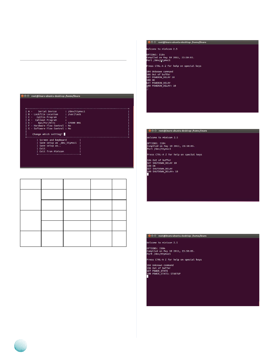
1. Set the delay time for power-on delay:
>SET POWERON_DELAY 4 (Set powe-on delay to 4
seconds)
>OK (System response)
>GET POWERON_DRLAY (Get the power-on delay time)
in seconds
>POWERON_DELAY=4 (System response)
The above command sets POWERON_DELAY =10
The above command sets SHUTDOWN_DELAY=10
2. Read the current power state
GET POWER_STATE (Get power state command)
POWER_STATE=STARTUP (System response)
The above command reads the current power state.
3. Read/write digital output state
>SET DIGITAL_OUT 3 (set digital_out bit 0=1 and digital_
out bit 1=1)
>OK