Chapter 1, Chapter 1: introduction, Introduction – Lanner VES-500 User Manual
Page 4: System specification
4
Introduction
Chapter 1
Embedded and Industrial Computing
Chapter 1:
Introduction
Thank you for choosing the VES-500. The VES-500 is
Lanner’s flagship Single Board Computer. It features
Freescale IMX6 series processors.
This computer-on-module consists of a motherboard
populated with the Freescale® iMX6™ series processor,
providing a rich I/O capabilities and flexibility via high-
bandwidth interfaces such as Mini-PCI Express sockets,
Serial ATA, and Hi-Speed USB 2.0 connectivity.
It also contains advanced I/O connectors as the following
listed:
-built-in GPS (provided by Neo-6Q) and G sensor
-Internl MIPI (Mobile Industry Processor Interface)
connector
-Wide range of DC power input from 9V to 30V, suitable
for vehicular 12V or 24V battery with Ignition control (with
VEK-IGN01 ignition board).
-CAN bus Connector via DB-9 female connector
-Dual Mini-PCI Express Sockets (one comes with a SIM card
reader for 3G Internet service)
-External SIM card reader
-External SD card reader
-Line-out/microphone jack as well as HDMI connector
The platform is supported by a Linux BSP as well as
multiple third party operating systems and reference
implementations that allow fast time to market and rapid
prototyping. We include development instructions in
the BSP folder in the Driver and User Manual CD. More
information can be found at
http://www.freescale.com/
webapp/sps/site/prod_summary.jsp?code=i.MX6Q
. Note
that some documentation and software may require you
to register first.
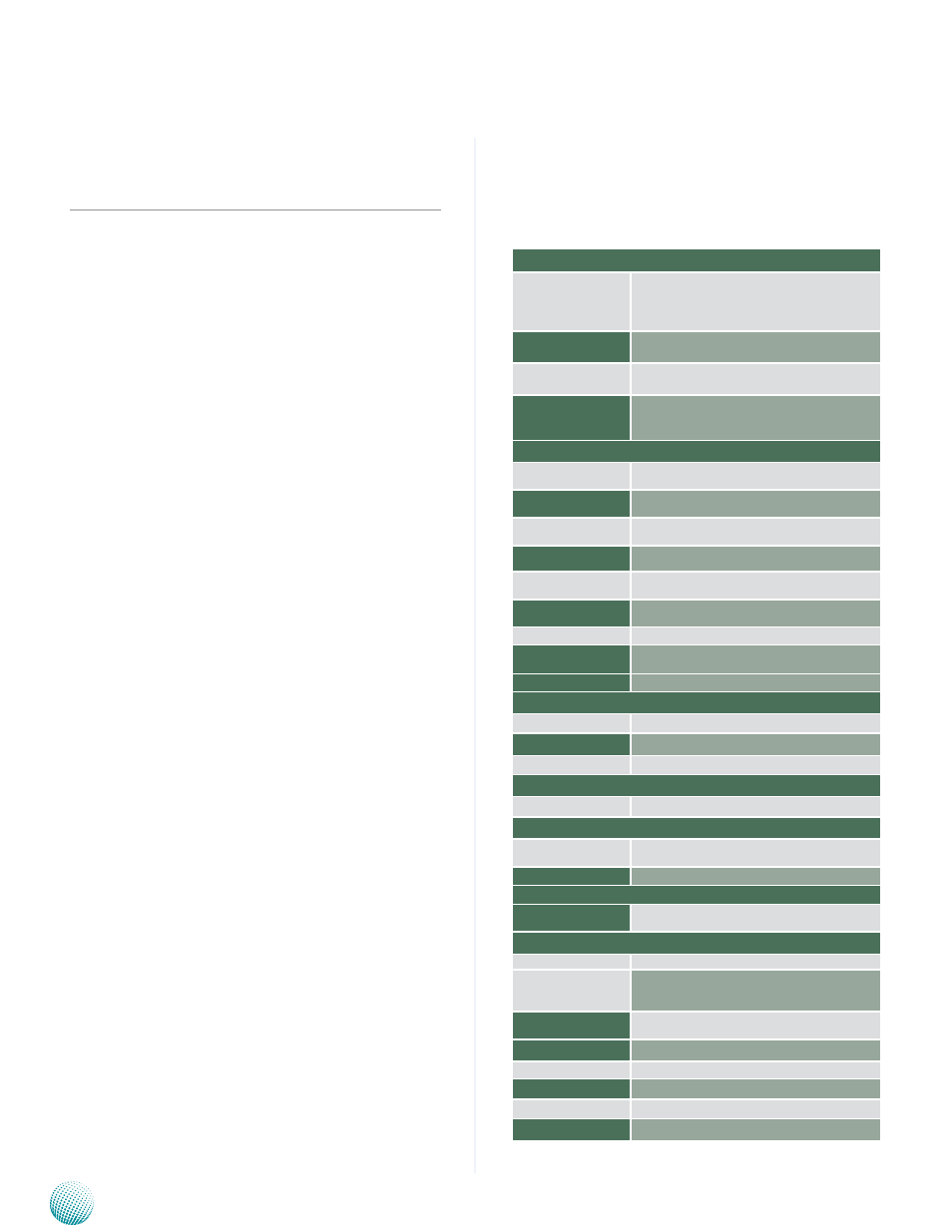
System Specification
System
CPU
Freescale iMX6 series processors: quad Core (VES-
500A)/dual core (VES-500B)
System Memory
Onboard DDR3 SDRAM
Storage
Onboard 4GB eMMC flash and SD card socket
Expansion
Power Ignition board: VEK-IGN01
Power over Ethernet: VEK-PDM01
I/O
DC-in and Power Ignition
Connector
3-pin power-in connector with ignition control pro-
vided by ignition board VEK-IGN01
MCU Programming and
Digital I/O
D-sub 9 Male Connector for MCU programming and
digital I/O function provided by VEK-IGN01
USB
2x USB 2.0 type A (host and Usb On-The-Go, 1x5 pin
header
Mini-PCIe Expansion
2 Mini-PCIe connector supporting only USB interface;
one comes with a SIM card reader
CAN (Controller Area
Network) BUS
CAN bus connector via DB-9 female
MIPI
Internal MIPI (Mobile Industry Processor Interface)
connector (reserved)
SATA
1 SATA drive and power connector
GPS
1x GPS chip (Neo-6Q) with SMA connector for
antenna
G Sensor
G Sensor
Display
Chipset
Intel Integrated Graphics
LVDS
1 x 2x15-pin 24-bit LVDS output
HDMI
1 x HDMI connector
Audio
Connectors
Line-out and Mic-in audio jack
Ethernet
LAN Chip
1 x Atheros AR8031PCI express
1x Ethernet controller
Ethernet Interface
RJ45 with LED, 10/100/1000Mbps
Console
Internal Serial Port
One internal 3-pin pin header for serial communica-
tion
Mechanical & Environmental
Power requirement
+12V DC-in
Optional power require-
ment (with PoE board
VEK-PDM01)
9~30Vdc in for wide range power input with MCU
controlled ignition function
Optional PoE (PD)
Powered device (PD for PoE) with default power
request 25W (802.3at)
Operating Temperature
-20 ~TBD°C (depending on chassis design)
Storage Temperature
-20 ~ 70°C (-4 ~ 158°F)
Operating Humidity
5% ~ 95% Relative Humidity, Non-condensing
Size (L x W)
230 mm x 145mm
Weight
0.2 kg (0.44 lbs)