Chapter 3, Motherboard information, Connectors and jumpers list – Lanner VES-500 User Manual
Page 12
12
Motherboard Information
Chapter 3
Embedded and Industrial Computing
Connectors and Jumpers List
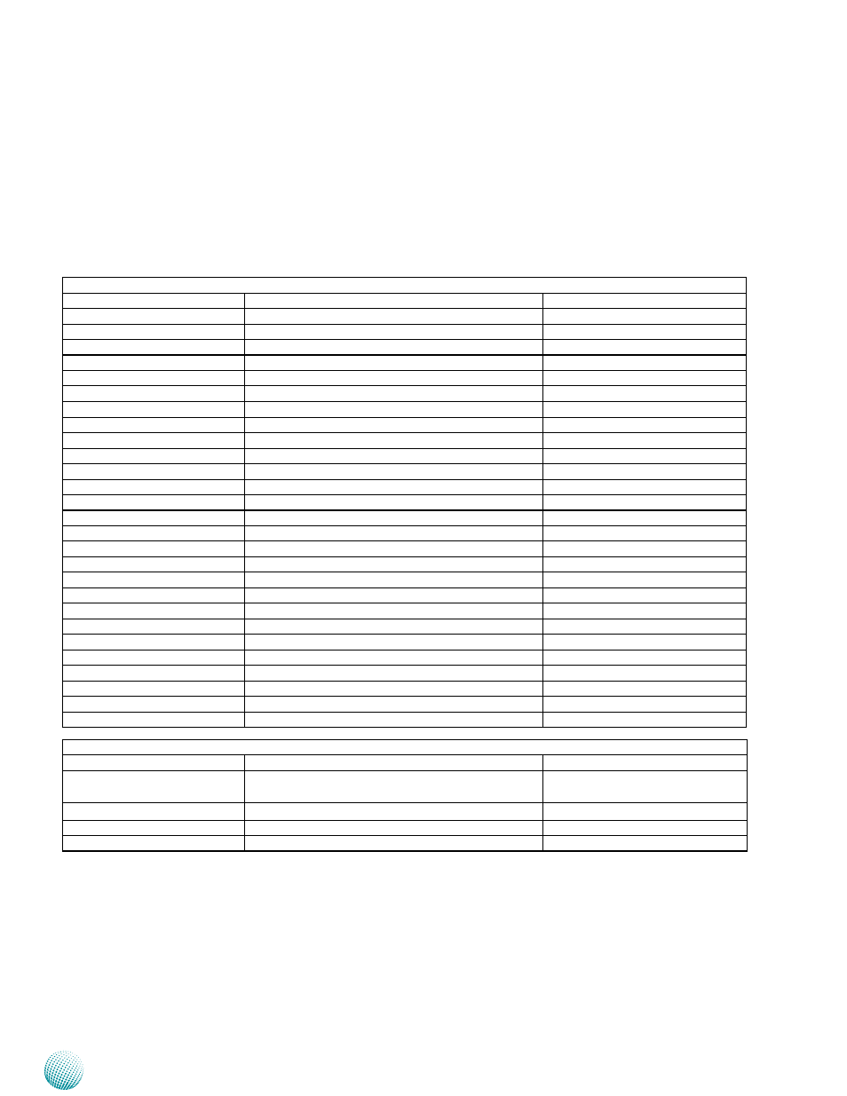
The tables below list the function of each of the board
jumpers and connectors by labels shown in the above
section. The next section in this chapter gives pin
definitions and instructions on setting jumpers.
Table 3.1 Connector List for VES-500 Board
Labels
Function
Pin Definition Reference Page
CAN1
CANbus Connector
P14
COM1
Serial COM Port
P13
CON1
LVDS Power Connector
P13
CON2
USB Connector
P13
DCIN1
DC-in Jack
P14
FRONT1
Front Headphone Connector
P15
HDMI1
High-Definition Multimedia Interface
P14
HOSTUSB1
Host USB Connector
P15
IGNIO1
Ignition Board Connector
P15
JTAG1
JTAG Connector
P14
LAN1
Ethernet LAN Connector
P13
LANIO1
PoE (PD) module
P15
LVDS1
Low-voltage Differential Signaling Connector
P14
MIC1
Microphone Connector
P15
MIPI1
Mobile Industry Processor Interface
P14
MODESLT1
Boot Mode Selection
P13
MPCIE1
Mini-PCIe Connector
P16
MPCIE2
Mini-PCIe Connector
P16
OTGUSB1
On-the-Go USB Connector
P15
PS4S1
SATA Power Connector
P13
RST1
Reset Button
P13
SATA1
SATA Drive Connector
P13
SDC1
SD Card Reader
P14
SIM1
SIM Card Reader
P15
SOTGM1
OTGUSB1 master/slave Selection
P15
SW1/SW2
System Boot Device Selection
P13
SW3
RST1 Function Selection
P13
Table 3.2 Connector List for VEK-IGN01 Board
Labels
Function
Pin Definition Reference Page
DGIO1
External Connector for MCU Programming and
Digital I/O
P17
IGNIO1
Connector to the Main Board
P17
PRJK1
DC-in Power Connector
P17
SW1
MCU (Microcontroller) Function Selection
P17