Chapter 3, Motherboard information – Lanner VES-500 User Manual
Page 15
15
Motherboard Information
Chapter 3
Embedded and Industrial Computing
Microphone Connector (MIC1):
Ignition Board Connector (IGNIO1): It is for connecting
the power ignition board—VEK-IGN01.
PoE power-device (PD) module Connector (LANIO1): It
is for connecting the POE powered device (PD) board VEK-
PDM01 or the VEK-TFM01.
Front Speaker Connector (FRONT1): Theses pin headers
provide function for speaker/headphone connection.
Pin No.
Pin Name
1
GND
2
MIC_RAW
3
GND
4
MICROPHONE_DET
5
MICBIAS2_RAW
+12V DC-in Jack (DCIN1)
HOST USB Connector (HOSTUSB1)
On-The-Go USB Connector (OTGUSB1): The USB
OTG can perform both master and slave roles in USB
communications. Besides the 2 external USB type A
connectors, an internal pin header is provided for an
additional USB port.
OTGUSB1 Mode Selection (SOTGM1): It selects the
OTGUSB1 to be either the host (master) or the device
(slave).
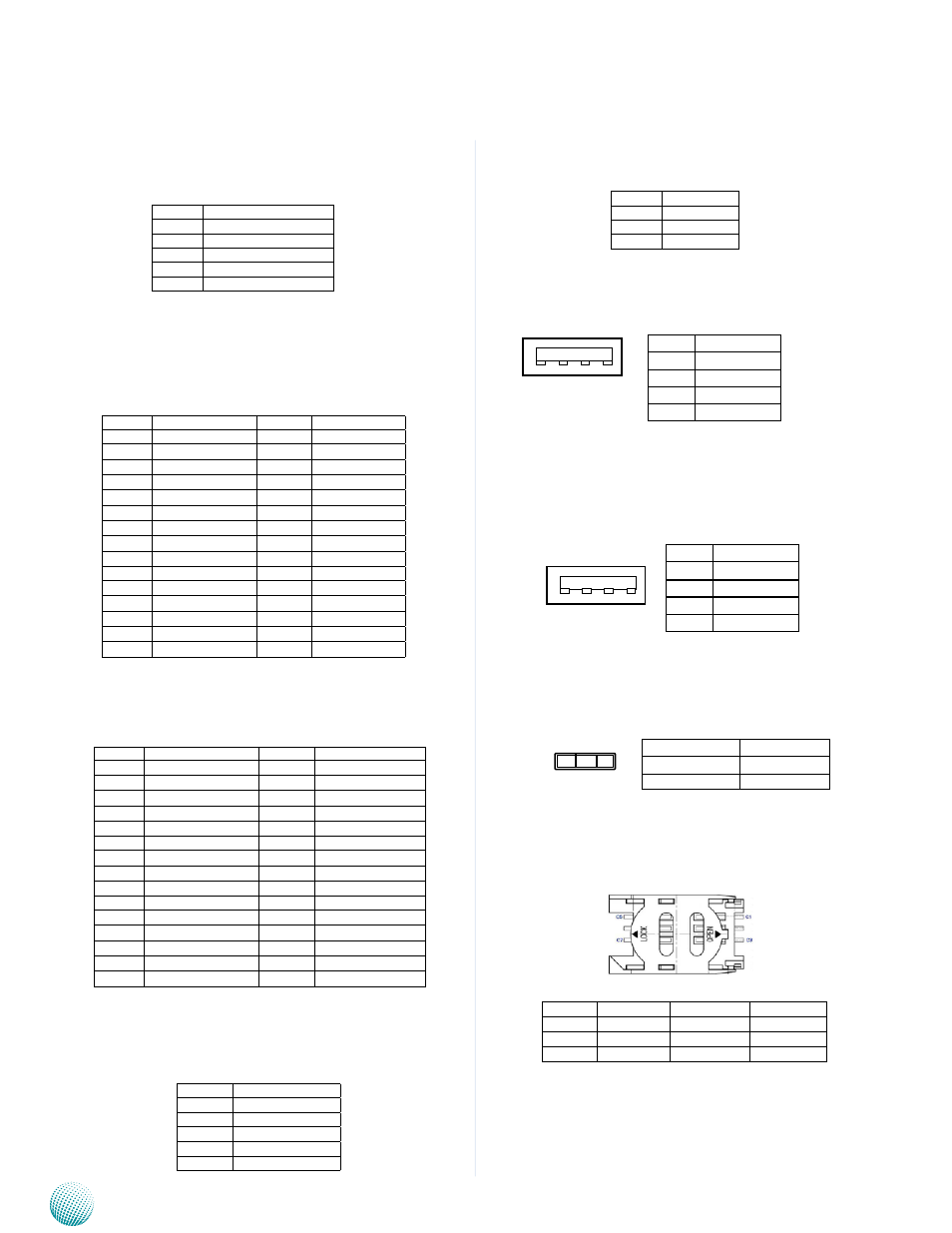
SIM Card Reader (SIM1)
Pin No.
Pin Name
1
+12V DC-IN
2
GND
3
GND
Pin NO..
Function
Pin NO.
Function
A1
GND
B1
P12V_SB1
A2
GND
B2
P12V_SB1
A3
GND
B3
P12V_SB1
A4
GND
B4
P12V_SB1
A5
GND
B5
P12V_SB1
A6
GND
B6
P12V_SB1
A7
GND
B7
P12V_SB1
A8
GND
B8
P12V_SB1
A9
GND
B9
N/A
A10
GND
B10
P5VA
A11
GND
B11
P5VA
A12
N/A
B12
N/A
A13
UART2_TX
B13
PWR_EN
A14
UART2_RX
B14
SYS_PG
A15
N/A
B15
N/A
Pin No.
Signal
1
GND
2
HP_L
3
GND
4
HEADPHONE_DET
5
HP_R
1 2 3 4
Pin No.
Signal
1
H1_VUSB
2
USB_HOST_DN
3
USB_HOST_DP
4
Ground
Pin No.
Signal
1
OTG_VUSB
2
USB_OTG_DN
3
USB_OTG_DP
4
Ground
1 2 3 4
Pin No.
Function
2-3
Host Mode
1-2
Device Mode
3 2 1
C1
C3
C5
C7
Pin NO.
Signal
Pin NO.
Signal
C1
UIM_PWR
C5
GND
C2
UIM_RST#
C6
UIM_VPP
C3
UIM_CLK
C7
UIM_DATA
Pin NO..
Function
Pin NO.
Function
A1
GND
B1
GND
A2
POE_MDI3N
B2
LAN1_MDI3N
A3
POE_MDI3P
B3
LAN1_MDI3P
A4
POE_MDI2N
B4
LAN1_MDI2N
A5
POE_MDI2P
B5
LAN1_MDI2P
A6
POE_MDI1N
B6
LAN1_MDI1N
A7
POE_MDI1P
B7
LAN1_MDI1P
A8
POE_MDI0N
B8
LAN1_MDI0N
A9
POE_MDI0P
B9
LAN1_MDI0P
A10
GND
B10
GND
A11
N/A
B11
PWR_EN
A12
GND
B12
P12V_SB1
A13
GND
B13
P12V_SB1
A14
GND
B14
P12V_SB1
A15
GND
B15
P12V_SB1