Chapter 3, Motherboard information – Lanner VES-310 V2 User Manual
Page 16
16
Motherboard Information
Chapter 3
Embedded and Industrial Computing
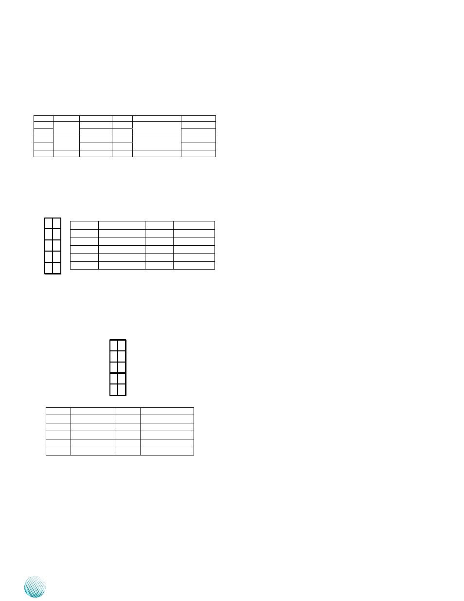
Additional Front Panel LED Connectors (J1): Theses
pin headers can be used as a backup for the following
functions: Hard disk LED, Reset Button, and Power LED
indicator. The front panel already provides access to some
of these functions.
SPI-ROM Update Connector (J3)
:
Using the
appropriate cable to connect this 10-pin ISP pin header
connector, the user can update the SPI Flash soldered on
board.
LPC I/O bus (Port 80 output for Debug Card) (J4): It
is Intel proprietary connector for connecting a checkpoint
device to output checkpoints throughout Power-On self
test (POST) routine to indicate the task the system is
currently executing.
Pin No.
Description
Pin Name
PIN NO.
Description
Pin Name
1
HDD LED
HDD_LED+
2
Power LED
PWR_LED+
3
HDD_LED-
4
PWR_LED-(GND)
5
Reset Button
GND
6
Power-on Push Button
GND
7
Sys_Reset-
8
PWR_BTN-
9
Buzzer
Buzzer
10
GND
Pin NO.
Pin Name
Pin No.
Pin Name
1
CLK_33M_P80
2
LPC_LAD1
3
RST_80DGPT_N
4
LPC_LAD0
5
LPC_FRAME_N
6
+3.3V
7
LPC_AD3
8
GND
9
LPC_AD2
10
GND
Pin NO.
Pin Name
Pin No.
Pin Name
1
NC
2
NC
3
SPI_CS0
4
V_3P3_SPI
5
SPI_ICH_MISO
6
SPI_HOLD0_L
7
KEY
8
SPI_ICH_CLK
9
GND
10
SPI_ICH_MOSI
9
7
5
3
1
10
8
6
4
2
9
7
5
3
1
10
8
6
4
2