Chapter 3, Motherboard information, Jumper settings – Lanner VES-310 V2 User Manual
Page 13
13
Motherboard Information
Chapter 3
Embedded and Industrial Computing
COM1 Type Jumper Selection (SC1T1/SC1T2): Use
jumpers SC1T1 and SC1T2 to select COM1 communication
type.
Ring-indicator Jumper Setting (SC1T3): The Ring
indicator pinout of the RS-232 COM port (COMB1) can be
altered according to the following jumper settings.
VGA Interface Connector (VGA1): It is for
connecting the VGA interface cable (2x6 to female
DB15). The VGA is provided by the integrated GPU which
implements Intel® Graphics Media Accelerator 3150 which
supports the following features:
DirectX 9.0c Support:
•
MPEG2 Decode capability in Hardware
•
Dual Independent Display of VGA and LVDS
•
Intel® Dynamic Video Memory Technology 4.0
•
support
-Integrated single LVDS channel support resolution
up to 1280x800 or 1366x768
-Analog RGB display output up to resolution
1400x1050@60Hz
Directx* 9 compliant Pixel Shader* v2.0
•
Intel
•
® Clear Video Technology equipped including
MPEG2 Hardware Acceleration and ProcAmp
Development software support including OpenGL*
•
1.5 with Microsoft* Windows* and OpenGL* 2.0 with
Linux
SATA Connector (SATA1): It is for connecting a 2.5’’
SATA harddisk to be served as your system’s storage. It
supports rates up to 3.0 Gb/s (300 MB/s) with Integrated
AHCI controller
1
2
3
4
5
6
7
Jumper Settings
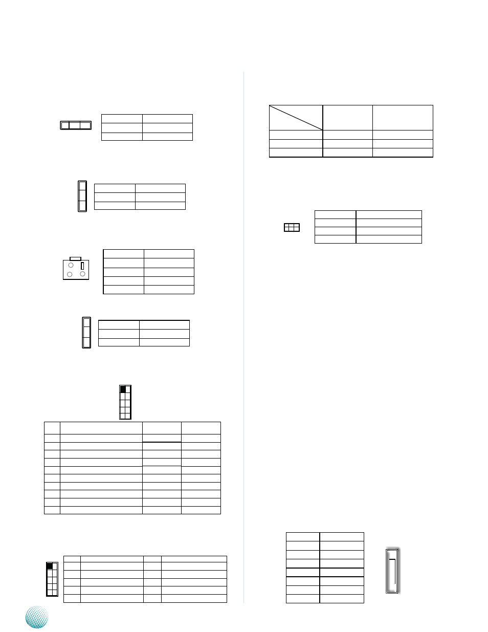
Clear CMOS jumper (CMOS1): It is for clearing the
CMOS memory.
Panel Voltage Selector (VLCD1): Use this jumper to
adjust the 5-pin LCD inverter power output.
4-pin Reset or Power-on Push Button (PSBTN1):
This button can be pushed to power up or reset the
system depending on the jumper setting (J2).
PSBTN1 Jumper Selection (J2): It is used for selecting
the PSBTN1 push button’s function.
RS-232 COM Port(COMB1, assigned as
COM1): It is for connecting the RS-232 serial port inter-
face cable. It also supports RS-422 and RS-485 communi-
cation protocols.
RS-232 COM Port(COMB2, assigned as
COM2): It is for connecting the RS-232 serial port inter-
face cable. Unlike COMB1, it only supports RS-232 com-
munication protocol.
Pin No.
Signal
1-2
Normal (Default)
2-3
Clear CMOS
1 2 3
Pin No.
Signal
1-2
+3.3V (Default)
2-3
+5V
3
2
1
2
4
1
3
Pin No.
Signal
1
Reset Signal
2
GND
3
GND
4
GND
P i n
No.
RS-232 Signal
RS-422.
RS-485
1
Data Carrier Detect (DCD#)
422TX-
DATA-
2
Data Set Ready (DSR#)
422TX+
DATA+
3
Receive Data (RXD)
422RX+
4
Request to Send (RTS#)
422RX-
5
Transmit Data (TXD)
6
Clear to Send (CTS#)
7
Data Terminal Ready (DTR #)
8
Ring Indicator (RI#)
9
Ground
10
Key
10
8
6
4
2
9
7
5
3
1
Jumper
COM1 Type
SC1T1
SC1T2
RS-232 (default)
1-2
1-5,2-6,3-7,4-8
RS-422
3-4
5-9,6-10,7-11,8-12
RS-485
5-6
5-9,6-10,7-11,8-12
10
8
6
4
2
9
7
5
3
1
Pin No.
Signal
PIN No.
Signal
1
Data Carrier Detect (DCD#)
6
Clear to Send (CTS#)
2
Data Set Ready (DSR#)
7
Data Terminal Ready (DTR #)
3
Receive Data (RXD)
8
Ring Indicator (RI#)
4
Request to Send (RTS#)
9
Ground
5
Transmit Data (TXD)
10
Key
Pin No.
Function
5-6 (default)
RS-232 Ring
3-4
Supply +12V to Device
1-2
Supply +5V to Device
1 3 5
2 4 6
Pin No.
Signal
1
GND
2
TX+
3
TX-
4
GND
5
RX-
6
RX+
7
GND
Pin No.
Functkon
1-2
Power button
2-3 (default)
Reset button
3
2
1