Chapter 3, Motherboard information – Lanner VES-310 V2 User Manual
Page 14
14
Motherboard Information
Chapter 3
Embedded and Industrial Computing
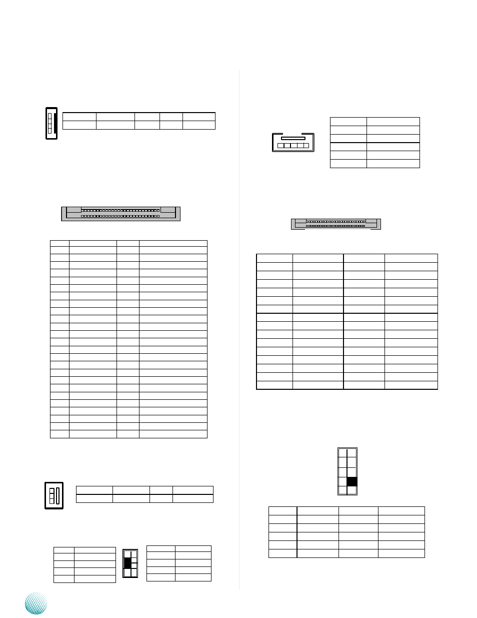
4-pin SATA Power Connector (PS4S1): It is used for
connectig the SATA power cord.
CF1: Compact Flash Connector (CF1): The
CompactFlash card slot is a type II connector and can be
inserted with type I or II CF card.
FAN Connector (FAN1): The 3-pin connector is for
connecting the system fan.
PS/2 Keyboard and Mouse Connector (PKMA1): It
is for connecting the PS/2 keyboard and mouse interface
cable.
Pin NO..
Function
Pin NO.
Function
1
GND
26
CD1-
2
DATA3
27
DATA11
3
DATA4
28
DATA12
4
DATA5
29
DATA13
5
DATA6
30
DATA14
6
DATA7
31
DATA15
7
CE1#
32
CE2#
8
A10
33
VS1#
9
OE#
34
IOR#
10
A9
35
IOW#
11
A8
36
WE#
12
A7
37
READY#
13
CFVCC3
38
CFVCC3
14
A6
39
CSEL
15
A5
40
VS2#
16
A4
41
RESET
17
A3
42
WAIT#
18
A2
43
INPACK#
19
A1
44
REG#
20
A0
45
DASP#
21
DATA0
46
DIAG#
22
DATA1
47
DATA8
23
DATA2
48
DATA9
24
WP
49
DATA10
25
CD2-
50
GND
52 2
51 1
50
26
25
1
PIN NO.
1
2
3
4
Signal
+12V
GND
GND
+5V
4
3
2
1
Function
Ground
+12V
FAN1 Status
PIN NO.
1
2
3
3
2
1
Pin No.
Pin Name
1
KBCLK
3
KEY
5
KEY
7
MSCLK
Pin No.
Pin Name
2
GND
4
KBDATA
6
MSDATA
8
+5VS
1
3
5
7
2
4
6
8
5-pin LCD (liquid-crystal display) inverter (INVER1):
It can be connected to supply the power to provide a
backlight to the monitor, thus enabling the user to view
what’s on the screen.
LVDS Connector (LVDS1): It is a 1-channel 18bits
LVDS connector.
Sound Interface Connector (SOUND1): It is provided
by the Realtek ALC886 HD audio codec. It supports Line-
in/Line-out with 2 channels of independent stereo sound
and microphone input.
PIN NO.
Function
1
+12V
2
+12V
3
+5V
4
Backlight Enable
5
GND
PIN NO.
Function
PIN NO.
Function
1
VCC_LVDS
2
VCC_LVDS
3
VCC_LVDS
4
VCC_LVDS
5
VCC_LVDS
6
VCC_LVDS
7
Reserve( SCL1)
8
Reserve( SCL)
9
Reserve( SDA1)
10
Reserve( SDA)
11
GND
12
NC
13
LCDAD0
14
NC
15
LCDAD0#
16
NC
17
GND
18
NC
19
LCDAD1
20
NC
21
LCDAD1#
22
NC
23
GND
24
NC
25
LCDAD2
26
LVD_A_CLK
27
LCDAD2#
28
LVD_A_CLK#
29
GND
30
GND
52 2
51 1
30
2
29
1
1
3
5
7
9
2
4
6
8
10
PIN NO.
Signal
PIN NO.
Signal
1
LOT-R
2
LOT-L
2
CO_GND
4
CO_GND
3
LIN-R
6
LIN-L
4
MIC-R
8
KEY
5
MIC-L
10
CO_GND