Chapter 3, Motherboard information, Connectors and jumpers list – Lanner VES-310 V2 User Manual
Page 12
12
Motherboard Information
Chapter 3
Embedded and Industrial Computing
Connectors and Jumpers List
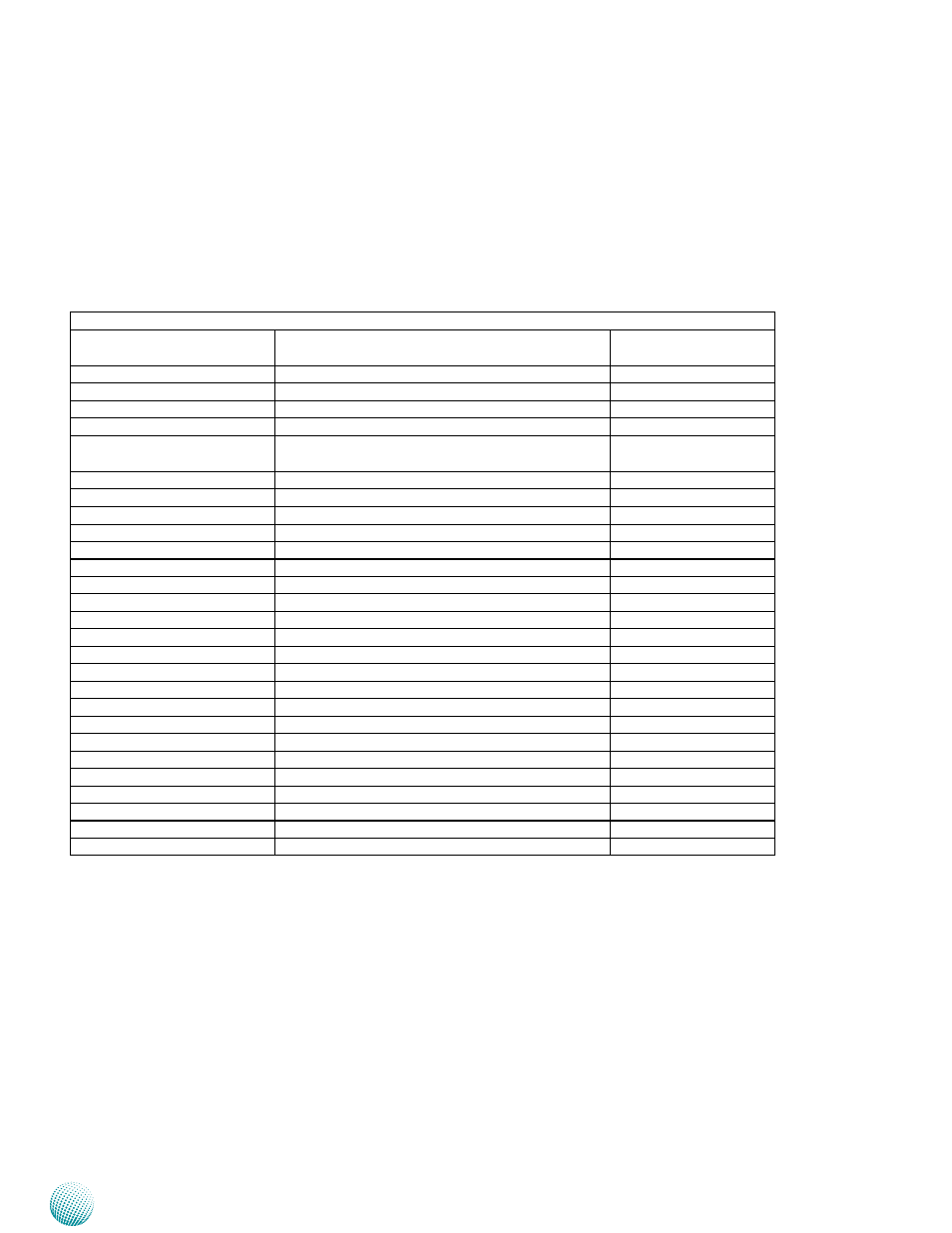
The tables below list the function of each of the board
jumpers and connectors by labels shown in the above
section. The next section in this chapter gives pin
definitions and instructions on setting jumpers.
Table 3.1 Connector List for LEB-7001 Board
Labels
Function
Pin Definition Refer-
ence Page
CF1
CF Socket
P12
CMOS1
Clear CMOS Jumper
P12
COMB1
RS-232 COM Port
P12
COMB2
RS-232 COM Port
P12
DCIN1
+12V DC-IN Power Socket for ATX Mode Power
Supply (DCIN1)
P12
DCJK1
12V DC-IN Power Connector
P12
FAN1
FAN Connector
P12
INVER1
5-Pin LCD Inverter
P12
J1
Additional Front Panel LED Connector
J10
Digital Input/Output Port
J2
PSBTN1 Jumper Selection
J3
SPI-ROM Update Connector
J4
LPC I/O bus (Port 80 output for Debug Card)
LPTA1
Parallel Connector
LVDS1
LVDS Connector
MPCIE1(optional)
Mini-PCIe 1X Connector
PKMA1
PS/2 Keyboard and Mouse Connector
PS4S1
4-pin SATA Power Connector
PSBTN1
4-pin Reset or Power-on Push Button
SATA1
SATA Connector
SC1T1/SC1T2
COM1 Type Jumper Selection
SC1T3
Ring-indicator Jumper Setting
SO-DIMM1
SO-DIMM Socket
SOUND1
Sound Interface Connector
USBB1
USB 2.0 Port
VGA1
VGA Interface Connector
VLCD1
Panel Voltage Selector